
Table of contents:
After assembling a prototype IoT device (in our example, a Wi-Fi relay) on a breadboard and connecting it to the 2Smart Cloud platform, we got a device that can already be used.
At the same time, inconveniences arise even for a DIY user: the device does not look aesthetic, and an additional 5V power supply is required. A device on a breadboard is all the more inappropriate for a vendor that plans to bring a product to market.
To obtain a full-fledged IoT device, it is necessary to modify the circuit so that the device works only from a 220V network. And also, place this circuit on a printed circuit board by placing it in the case.
Designing the PCB and housing for a Wi-Fi relay
In the example with a Wi-Fi relay from a DIY developer, there is no severe cost optimization task – it is about a tiny series of devices for himself and his friends. Therefore, we will briefly describe the components selection stage and the circuit board creation.
All materials for creating a Wi-Fi relay are available in the 2Smart Cloud public repository. If desired, you can assemble a similar device using this article as a tutorial.
How the device circuit has changed
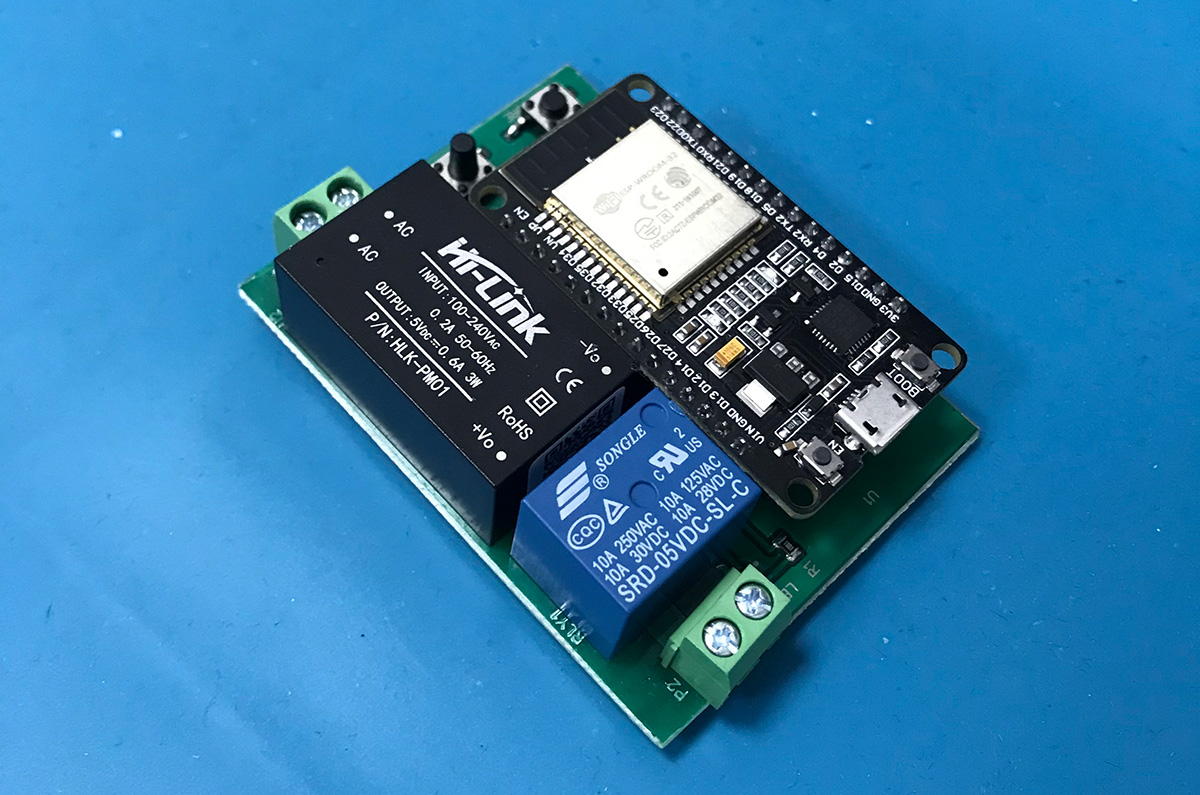
The only task in changing the circuit of the Wi-Fi relay is the need to give up an additional 5V power supply in the form of a USB cable. The device must operate only from a 220V network, turning on and off the device connected to it – for example, an ordinary table lamp.
To solve this problem, we add an additional element to the circuit – a voltage converter (power module) AC-DC 220V/5V. Instead of the relay module, a conventional relay is installed, which is controlled via a transistor (this upgrade is optional).
PCB design
Once the final version of the device circuit is obtained, it is possible to create a printed circuit board project. Use any popular board editor for this purpose – for example, easyeda.com.
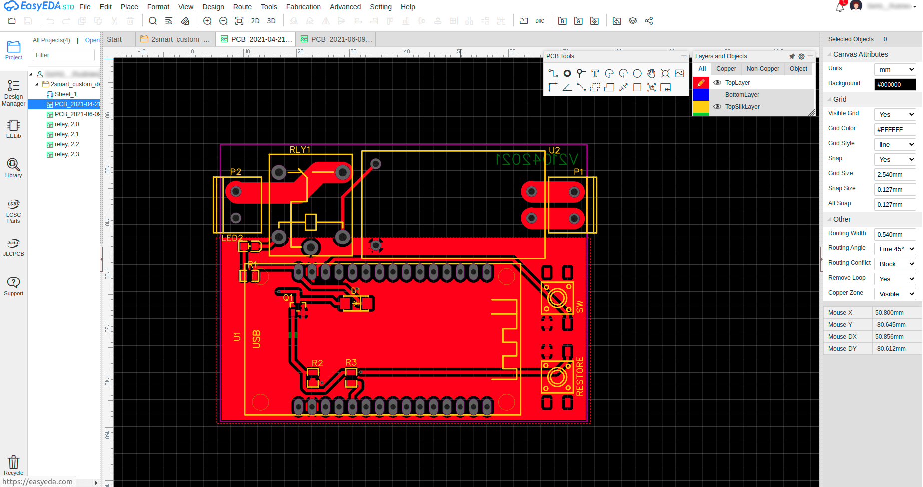
After creating the project, it remains to order the production of the required batch of printed circuit boards. There are many services for this – for example, jlcpcb.com.
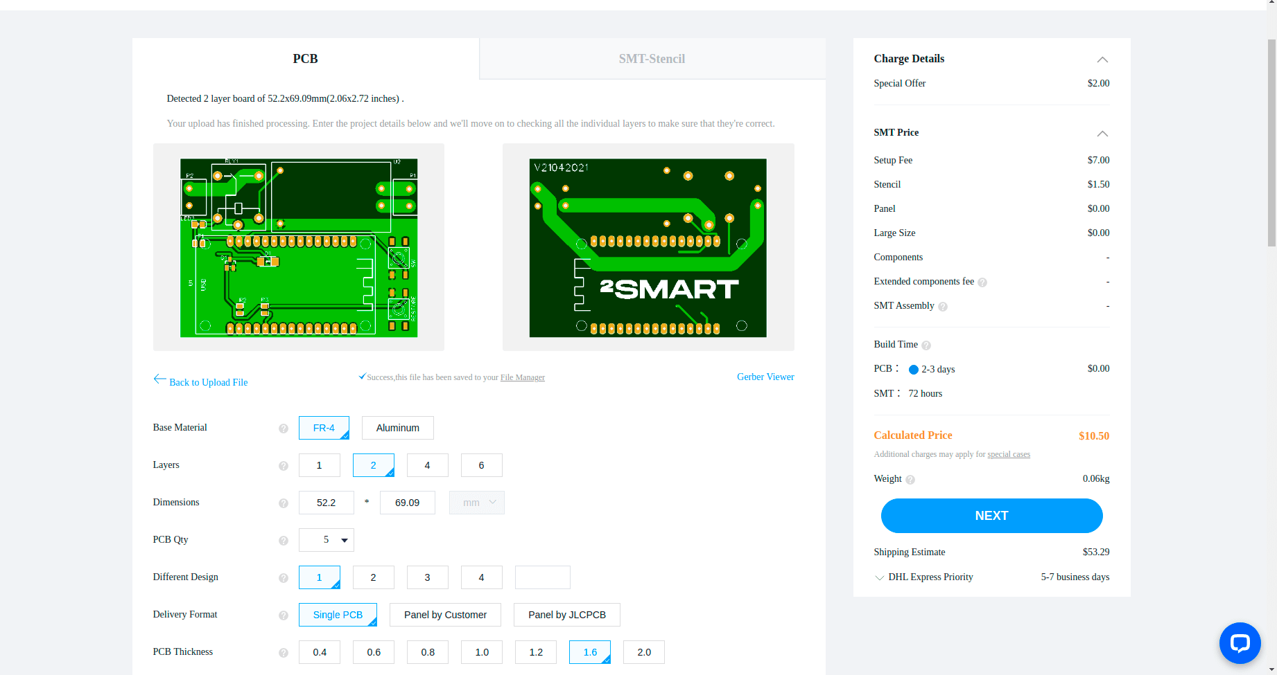
You also need to order the necessary components to assemble a batch of devices.
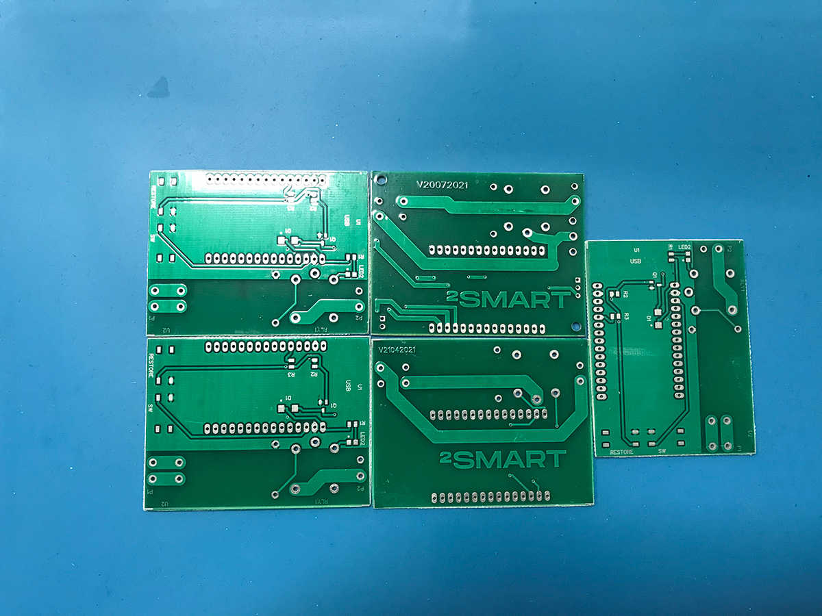
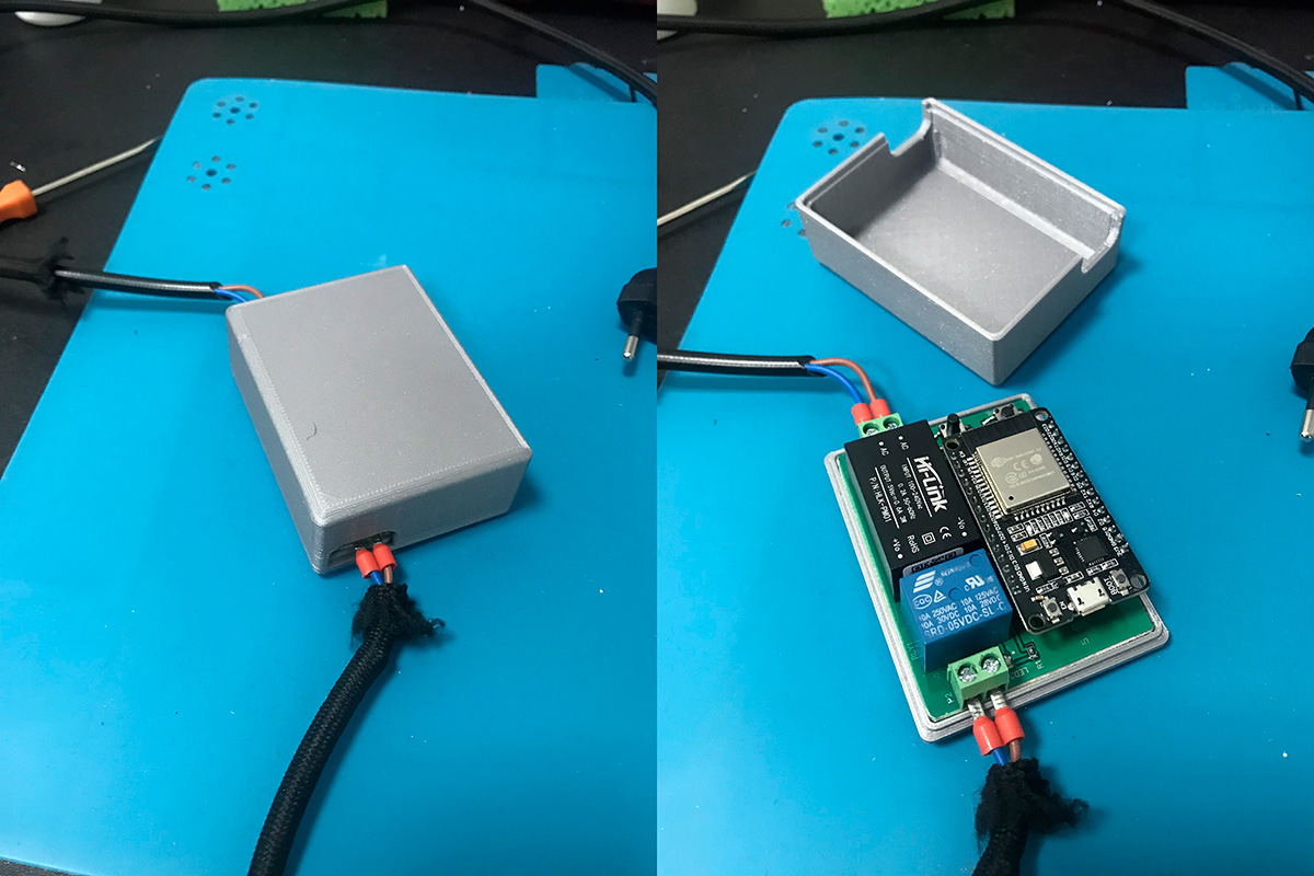
Knowing the device’s dimensions, you can also create a housing project in any 3D editor and print it on a 3D printer.
Having received ready-made printed circuit boards and components, it remains to assemble the devices with a soldering iron and place them in the housing.
Let’s collaborate
We’re empower your business with our technology expertise
Flashing devices
To flash the ready-made devices on a printed circuit board, the same Production code is used as for the prototype device on the breadboard. No changes are needed in most cases.
It makes sense to keep the prototype IoT device on a breadboard for testing new features. And the devices on printed circuit boards should be used in real conditions, upgrading them with new firmware versions if necessary.
When using ESPHome-based firmware, there is inconvenient to have to update each device manually via a USB cable. To automate the flashing process, you need to write a Custom firmware version that allows you to deliver updates over the air. We will talk about this in the following article of this series.
Links:
- 2Smart Cloud IoT platform – https://cloud.2smart.com/
- Materials for creating Wi-Fi Relay at public repository – https://github.com/2SmartCloud/2smart-cloud-esp32-relay
- Online PCB design tool – https://easyeda.com/
- PCB fabrication manufacturer – https://jlcpcb.com/
All articles about IoT device creation and support
- Learn your way around the IoT platform – create your first device and control it from your smartphone without an MCU
- How to create a Wi-Fi switch to control via a mobile app and Telegram bot
- How to build an IoT device using the 2Smart platform?
- How to create an IoT device on a printed circuit board and take it from prototype to finished product
- How to write SDK-based firmware for an IoT device
- How to update the firmware and mobile application of ready-made devices within 5 minutes
- Collection and analysis of statistics – a useful tool for product improvement
Don't forget to share this post!
Read Next


Let’s dive into your case
Share with us your business idea and expectations about the software or additional services.
