
Table of contents:
A Wi-Fi sensor installed in the room allows you to remotely monitor the air temperature. Based on this data displayed on the smartphone, it is possible to turn on or off a heating boiler or conventional heater, if they are also configured to be remotely controlled. It can also be useful to view the history of air temperature and humidity – especially if the room is not living, but, for example, a greenhouse. We will tell you how to assemble an elementary Wi-Fi temperature sensor in just 30 minutes and bind it to a mobile application for remote control.
Assembling the device
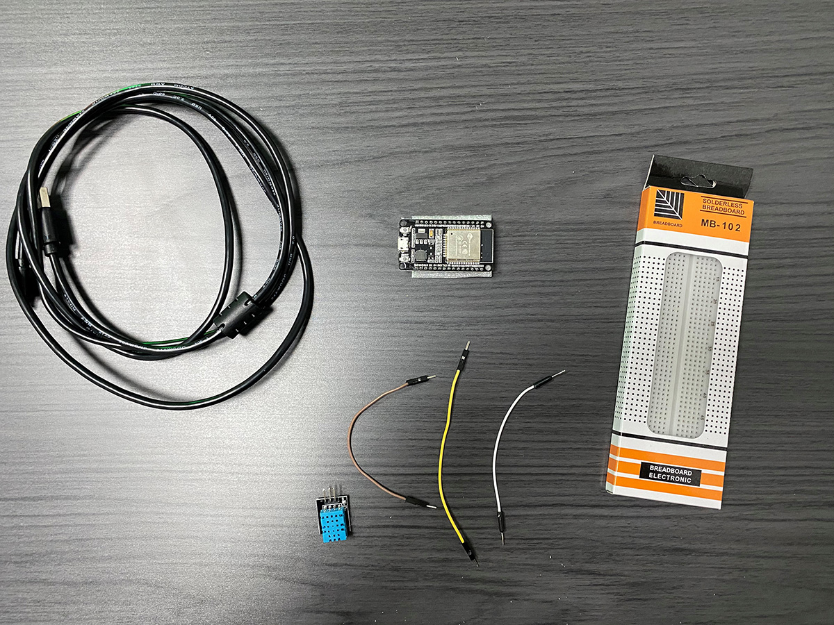
What is required to assemble a sensor like this:
- Breadboard – 1 pc.
- IoT platform ESP-WROOM-32 DevKit v1 – 1 pc. (any other platform variation with or without an ESP32 microcontroller on the Dev Board).
- Male to male jumper cable – 3 pcs.
- DHT11 humidity and temperature sensor – 1 pc.
- USB-micro USB cable.
All necessary components:
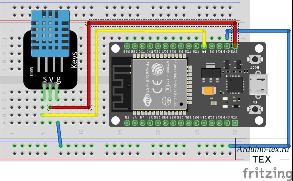
To assemble the device, we used the following example of a circuit found by searching for images on Google:
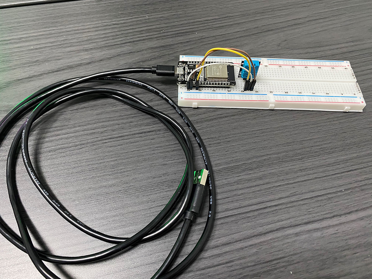
Here’s what happened as a result:
Making the “smart” assembled device
- Go to the vendor’s account using the link – https://cloud.2smart.com/. Log in to your account.

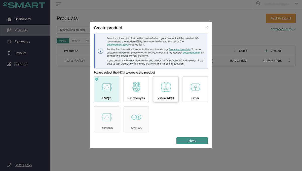
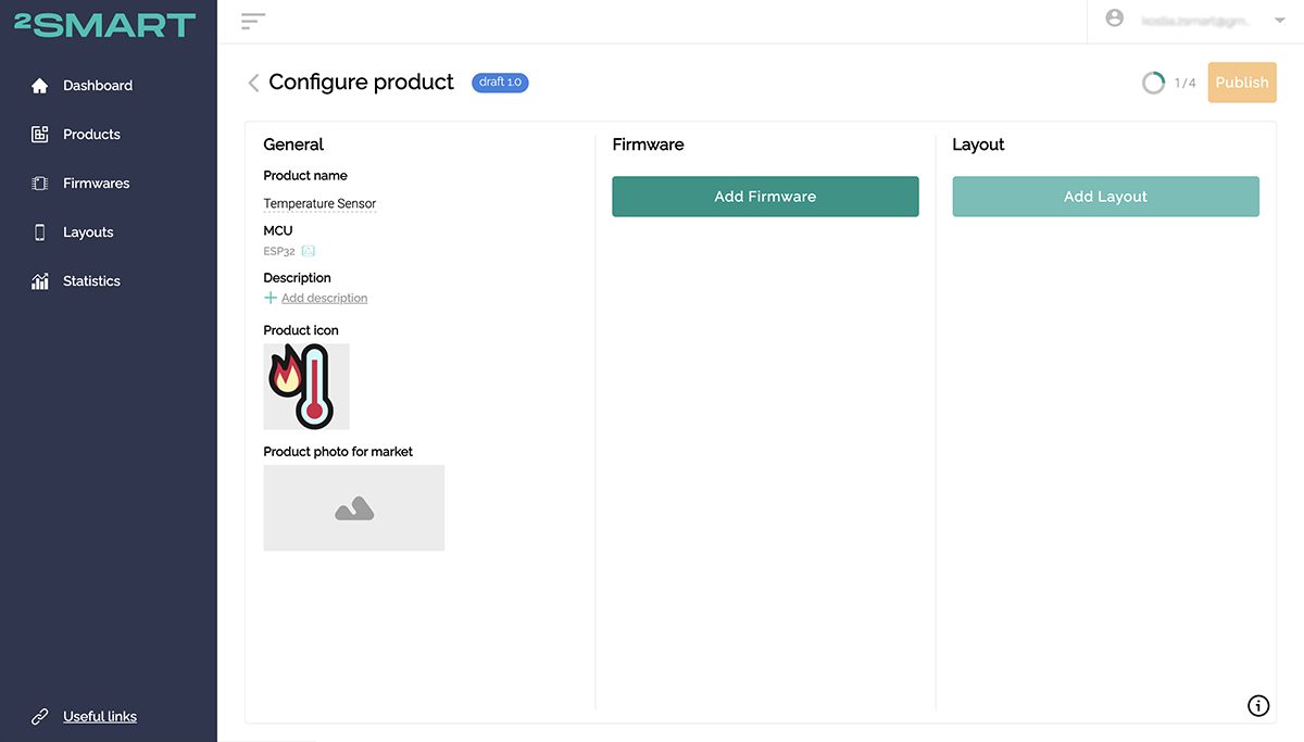
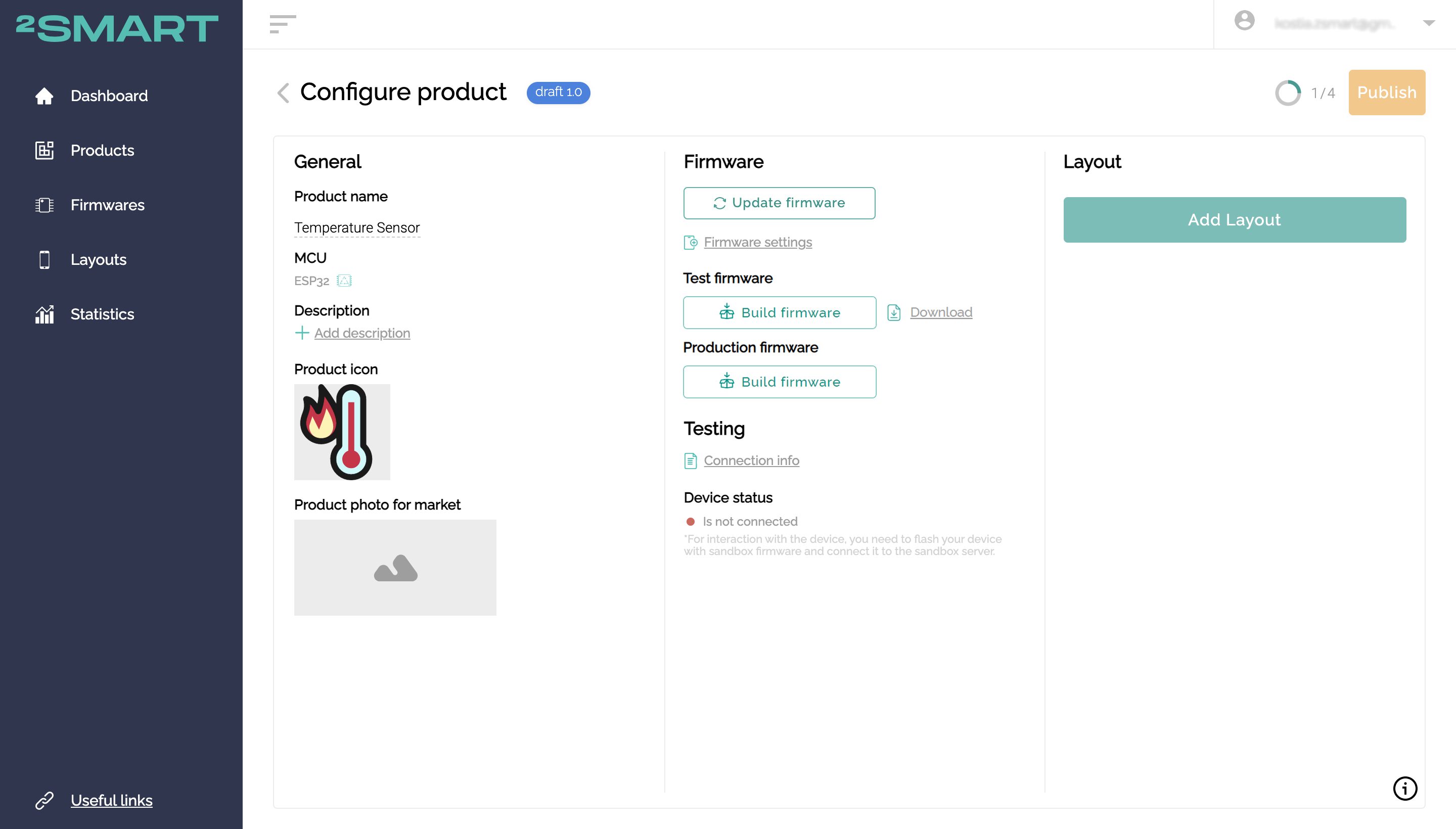
- On the Products page, click Add Product and select the ESP32 microcontroller.

- On the new product page, enter its name and upload the icon – with this data, the device will be displayed in the mobile application.
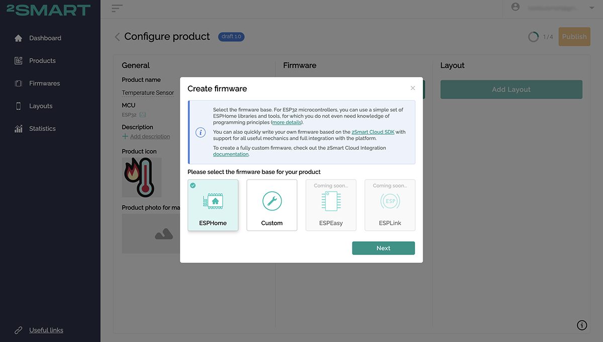
- Click ” Add Firmware” and select an ESPHome base for it.
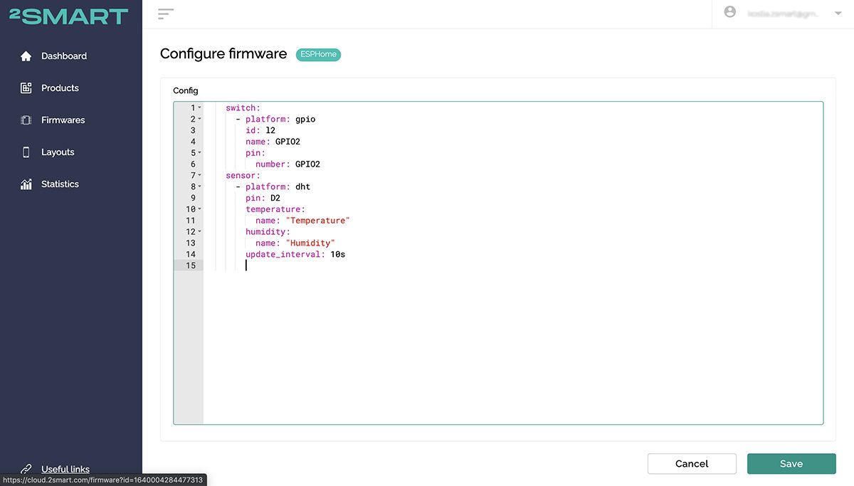
- Paste the following firmware code into the opened window:

switch:
- platform: gpio
id: l2
name: GPIO2
pin:
number: GPIO2
sensor:
- platform: dht
pin: GPIO15
temperature:
name: "Temperature"
humidity:
name: "Humidity"
update_interval: 10s
Explanation of the firmware code:
- The first six lines are the standard code for controlling the LED on the microcontroller.
- The next eight lines are the standard code for the DHT11 sensor taken from here. We’ve made two changes to this:
- changed the data update interval – every 10 seconds instead of every 60 seconds,
- the pin of the microcontroller to which the sensor is connected is indicated – in our case it is GPIO15.
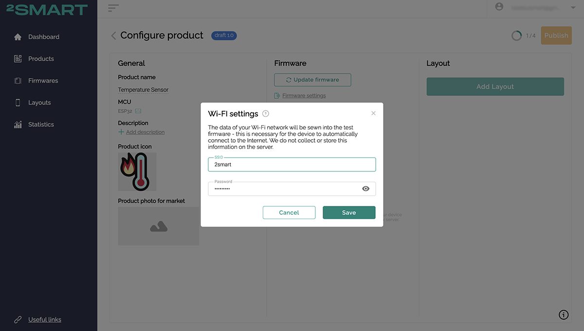
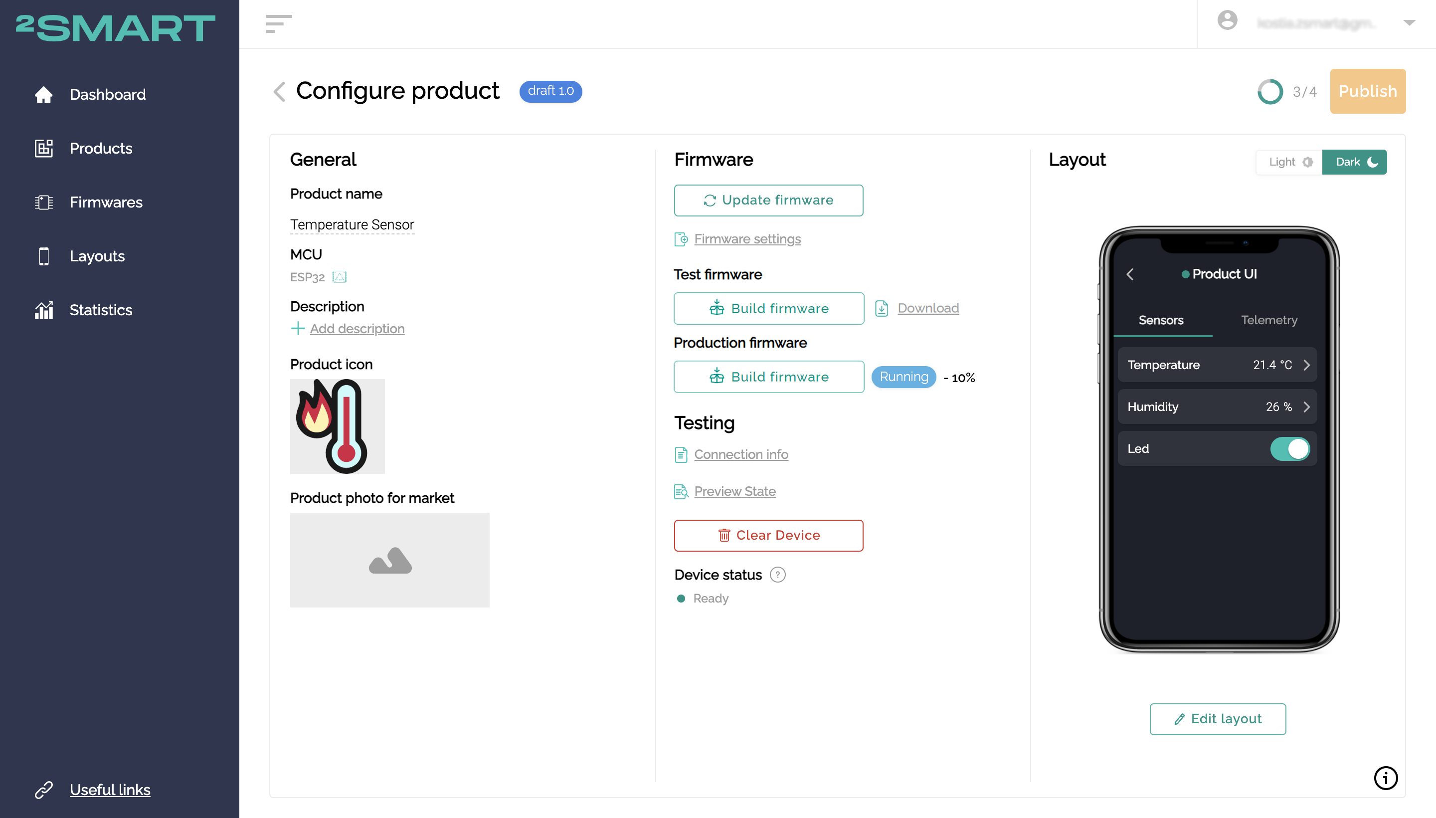
- Save the code configuration in the product setup window and then click Build Firmware for the test device. Specify the data for connecting to your Wi-Fi network – they will be embedded in the firmware code so that the device will immediately go online and connect to the platform.
- Wait for the firmware build and click “Download”.

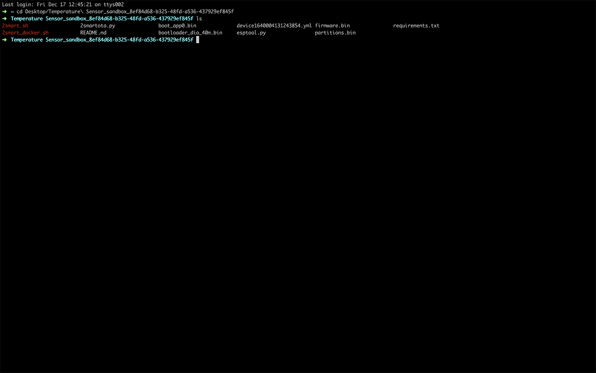
- Extract the downloaded archive, enter the folder with the received files and read the instructions for firmware in the readme.md file.
Flashing is available from Mac OS, Linux, and Windows devices – we used Mac OS.
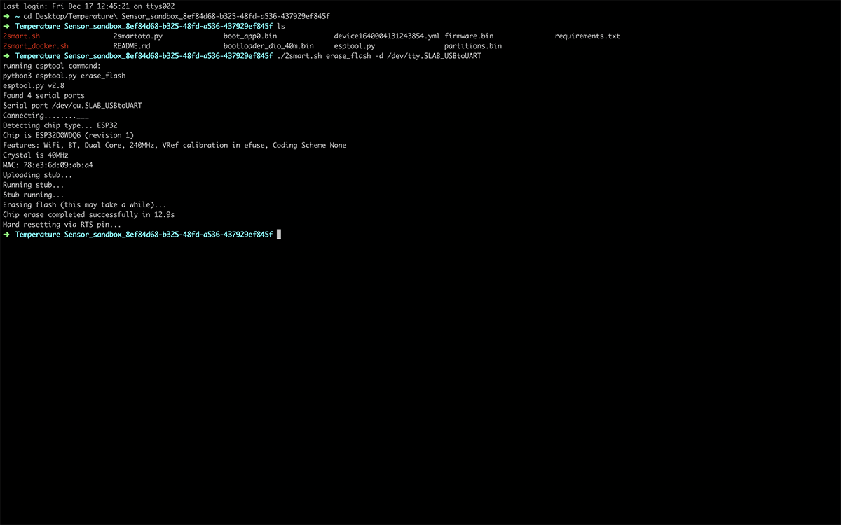
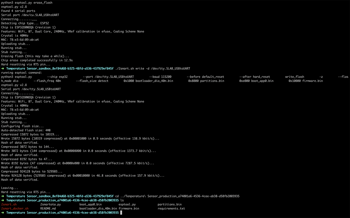
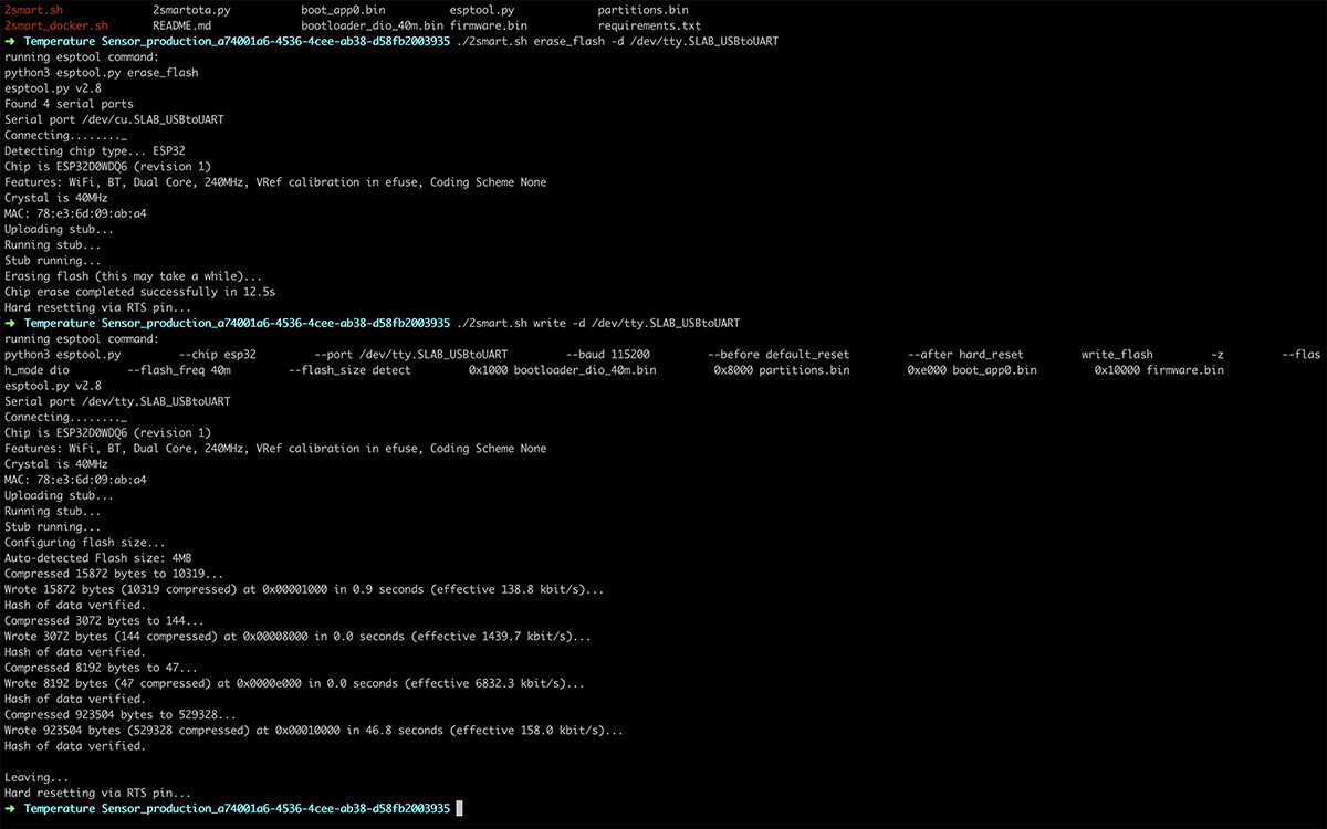
- Connect your device to your computer using a USB cable. Erase the microcontroller memory with the following command:
./2smart.sh erase_flash -d /dev/tty.SLAB_USBtoUART
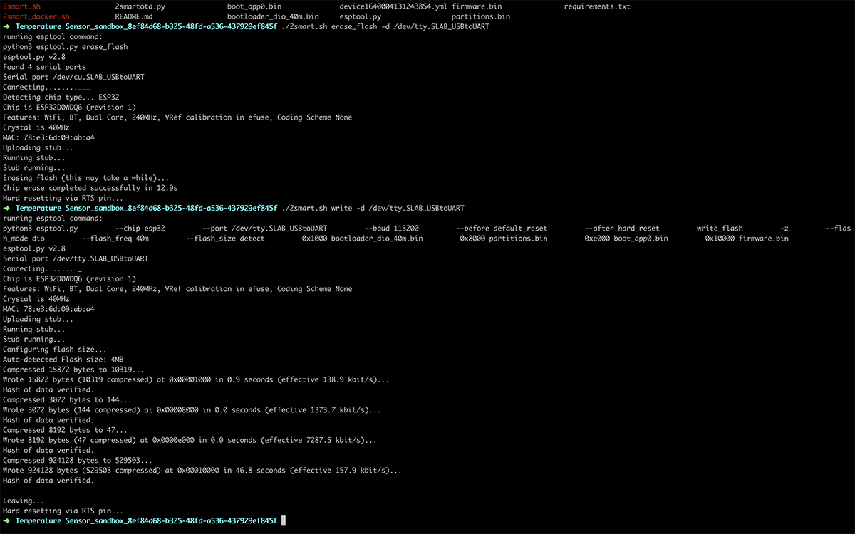
- Wait for the cleanup and run the firmware installing command:
./2smart.sh write -d /dev/tty.SLAB_USBtoUART
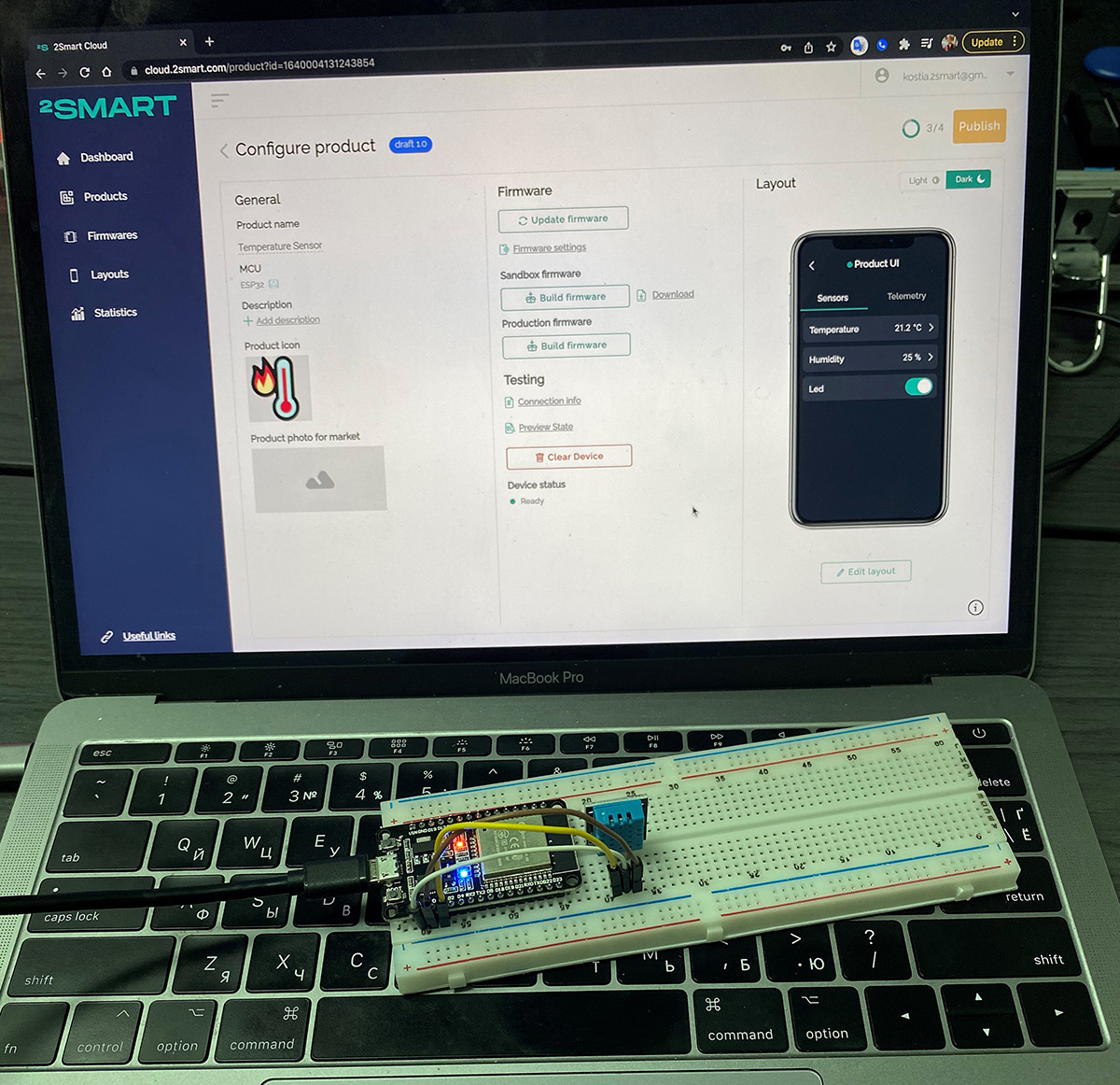
- After completing the firmware process, return to the platform – the device will automatically connect. A successful connection is indicated by green color and Ready status in the “Device Status” field.
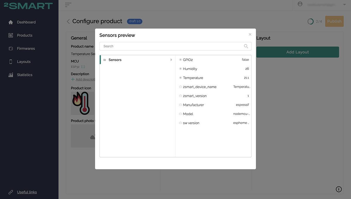
- Click “Preview state” – you will have access to the data of all sensors of your device, including the current temperature and humidity.
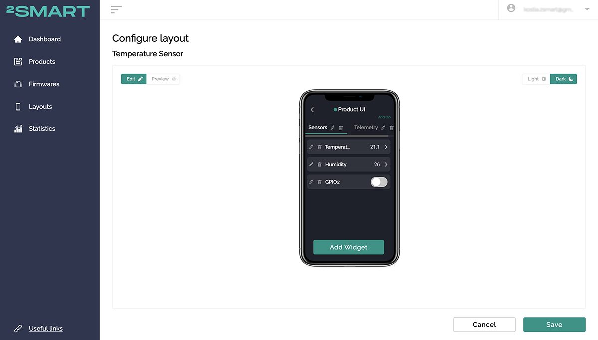
- Click “Add layout” – the mobile application emulator will open. Appropriate widgets are automatically created for all sensors on your device. You can customize the appearance of the application to your liking, including choosing different types of widgets instead of the default widgets and organizing the order of the widgets on the screen.
Please note that the sensor values are updated in real time already in the mobile application emulator. You can also control the device from the computer screen – in this case, the LED can be turned on / off.

Let’s collaborate
We’re empower your business with our technology expertise
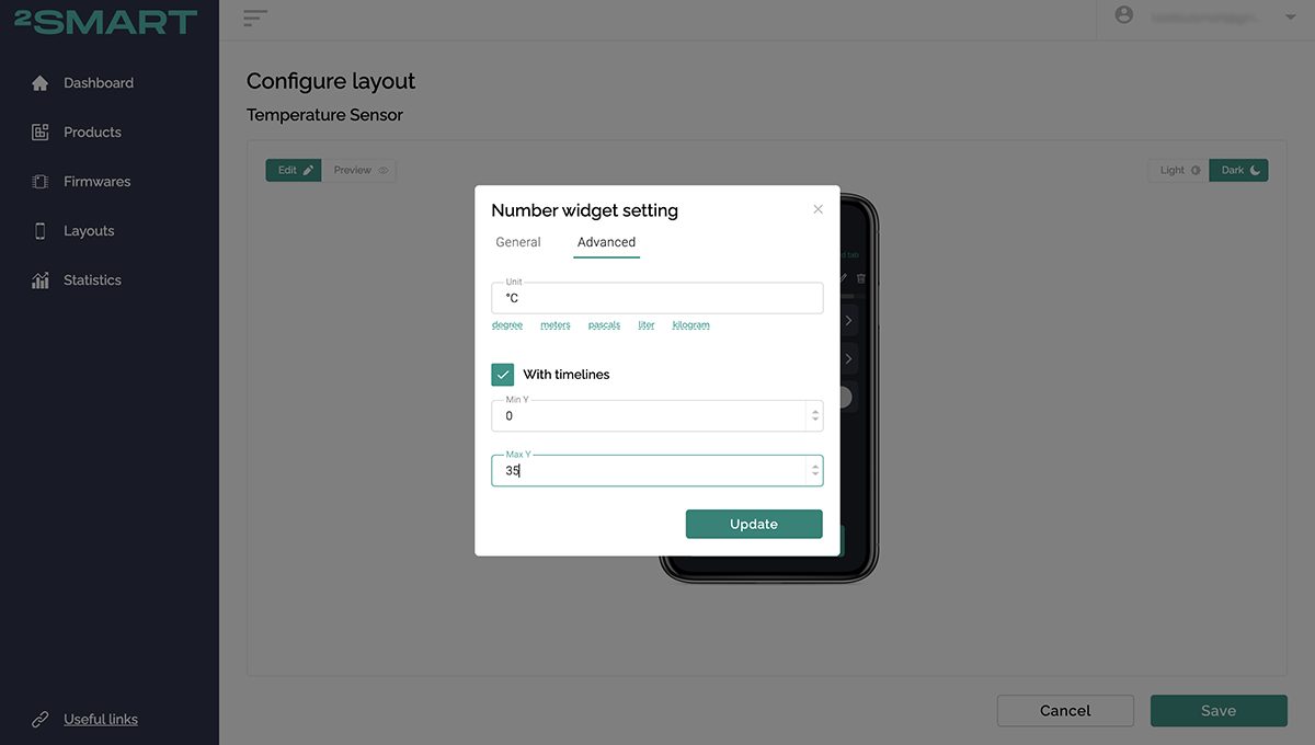
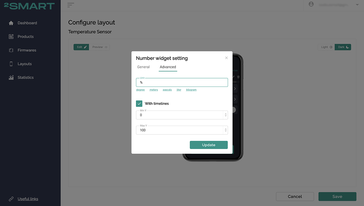
- Open the settings of the temperature and humidity sensors and make sure that the historical data collection checkbox is checked on the “Advanced” tab. It is also recommended to add units and boundaries along the vertical axis.
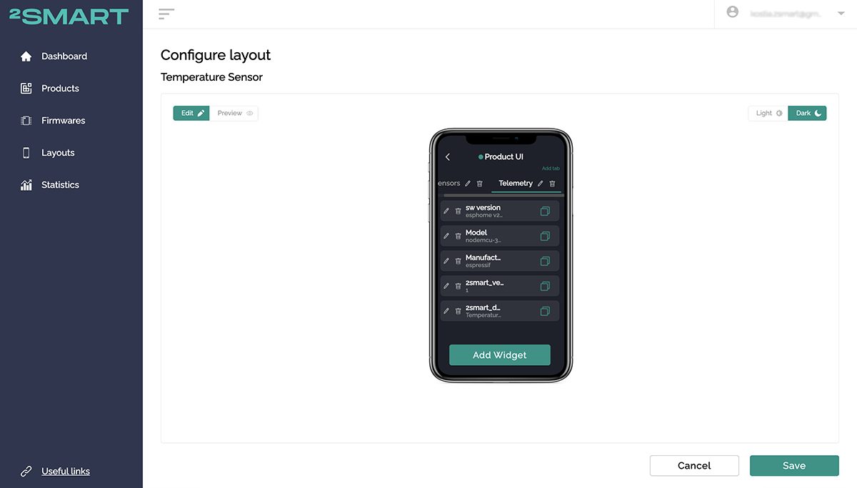
- Please note that in the mobile application, in addition to the widget screen, a telemetry screen with metadata is automatically created. It is not recommended to delete.
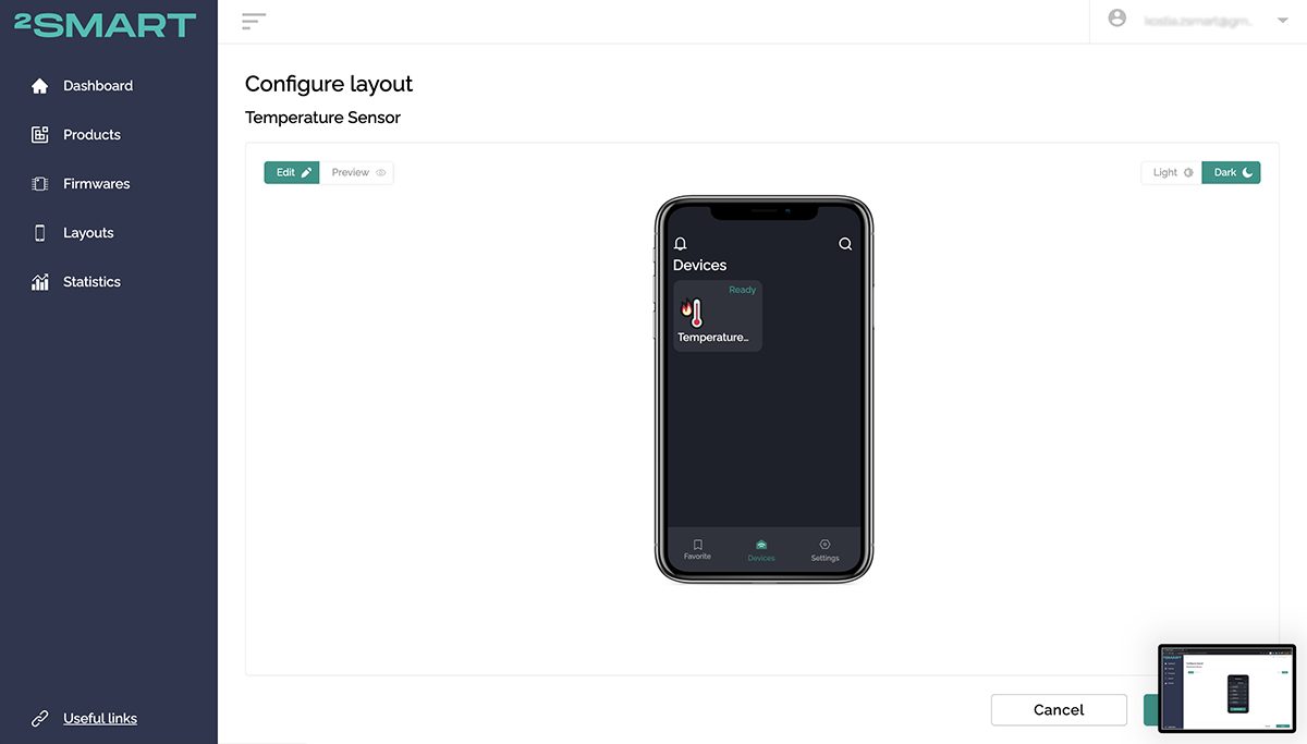
- By clicking the “Back” arrow in the mobile app emulator, you can see how the sensor will look in the list of connected devices.
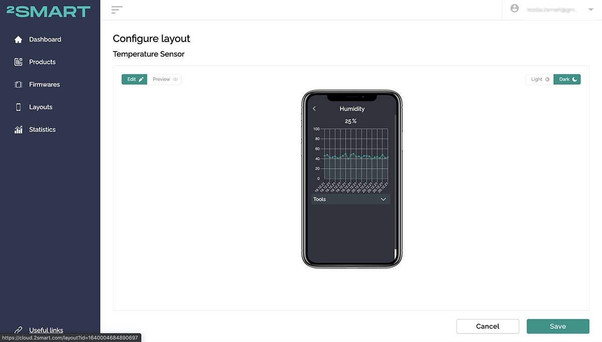
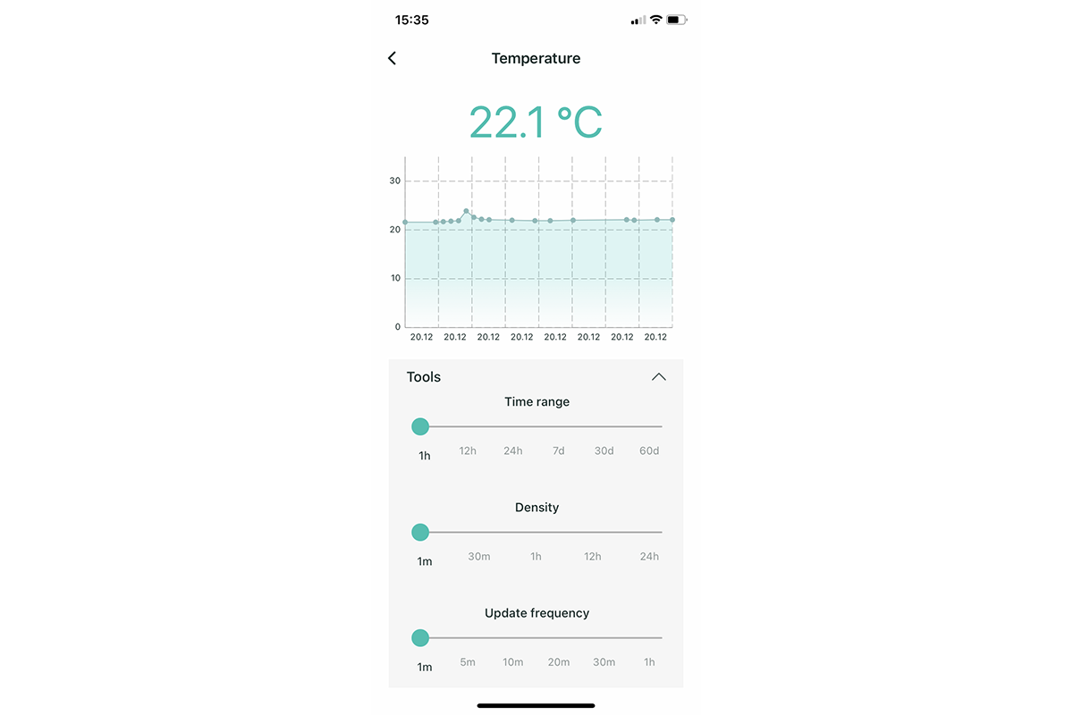
- Go back to the device management interface, go to the temperature and humidity widgets and see how the graphs with the history of the corresponding readings will look like. So far, you can only evaluate the appearance of the graph – its values themselves in the test mode have nothing to do with reality and are presented for clarity.
After you finish configuring the interface, click “Save”.
- Launch the 2Smart Cloud mobile app on your smartphone – most likely you’ve already used it to connect and control a virtual lamp. Log in using the email and password that you used when registering at the vendor’s account.
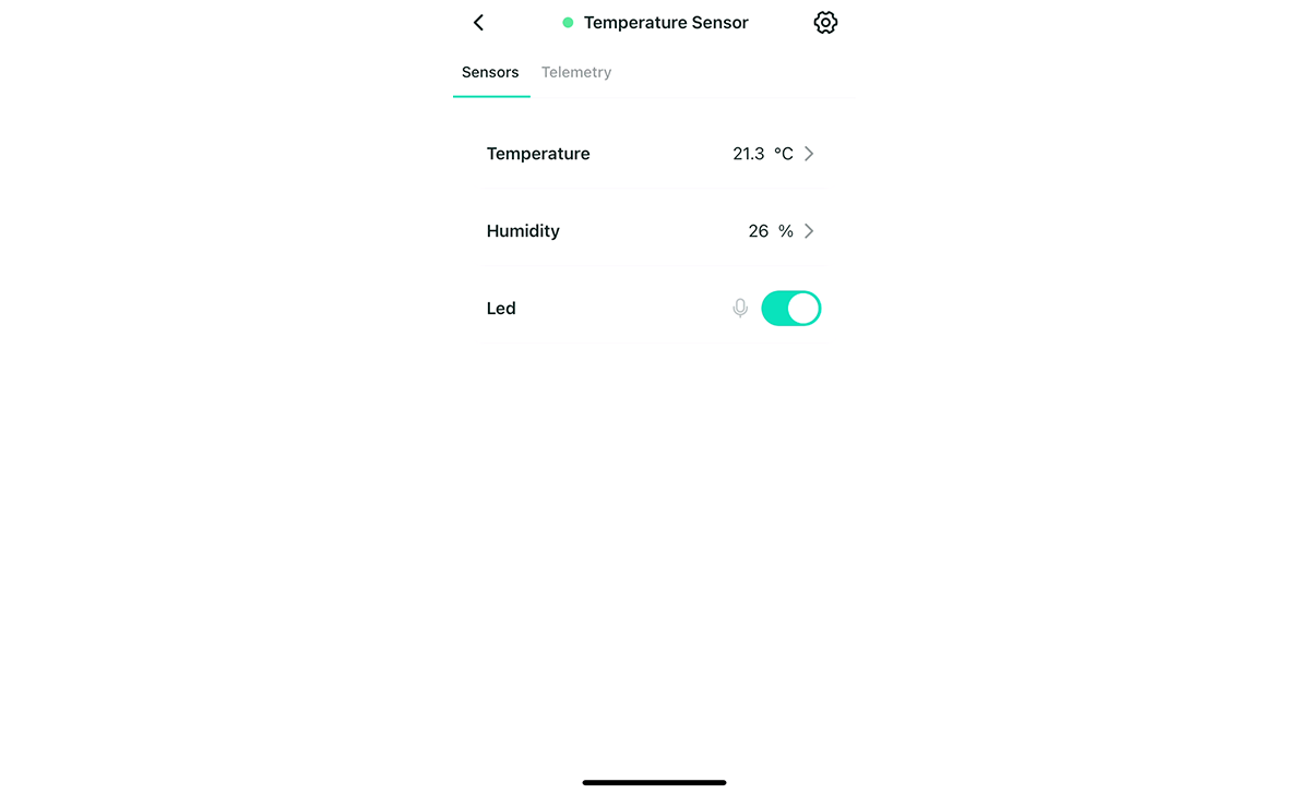
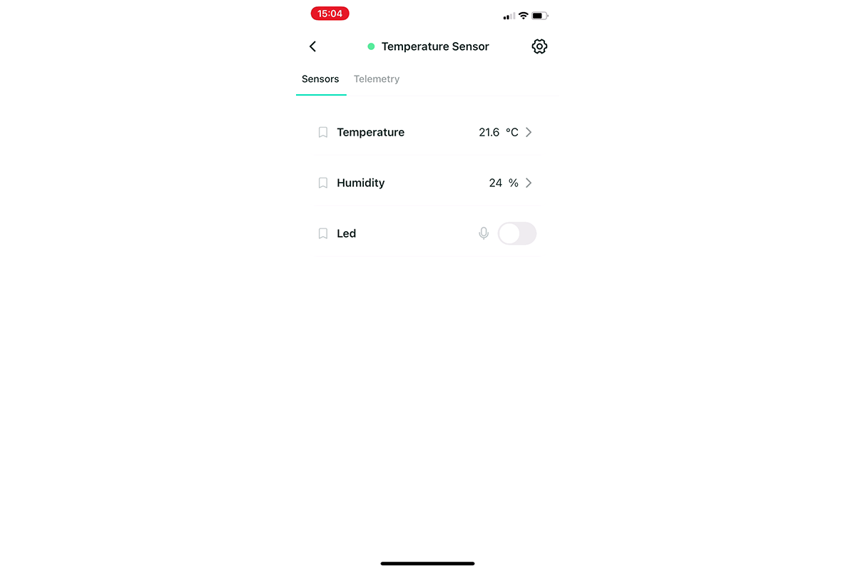
- Your new device is already showing in the app – make sure you can turn on / off the LED on the board and get the correct temperature and humidity sensor readings.


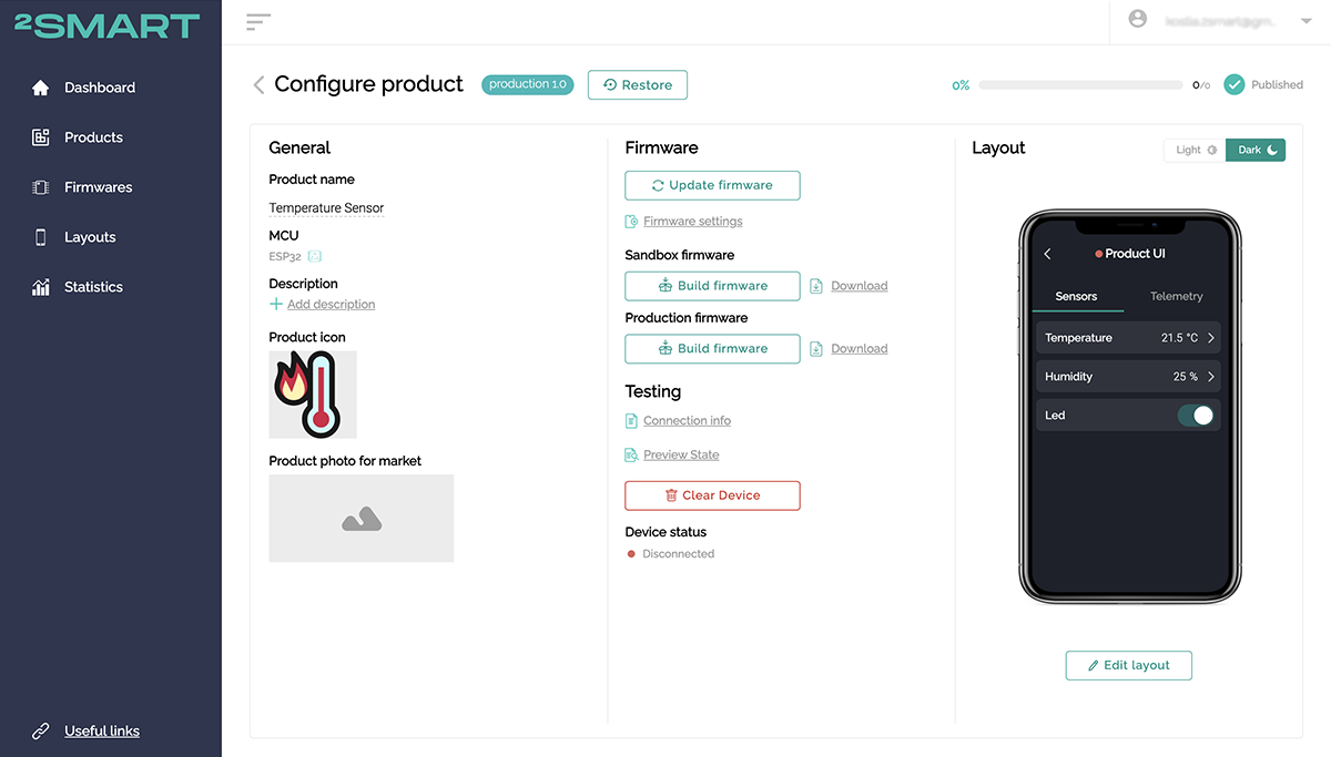
- Go back to the platform and click “Build Firmware” for the “Production” option. The production version of the firmware will be built, which will not contain the parameters of your Wi-Fi network and other specific lines of code needed to test the prototype. Download the archive that you received.

- Upload the Production device with the firmware similar to the Test firmware version. Remember to clear the microcontroller memory first.Use the following commands:
./2smart.sh erase_flash -d /dev/tty.SLAB_USBtoUART
./2smart.sh write -d /dev/tty.SLAB_USBtoUART
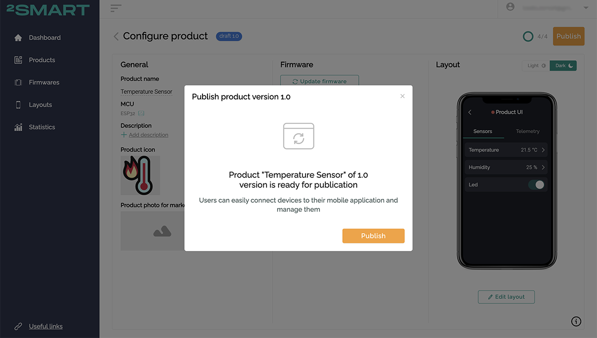
- Click Publish to start using your device.
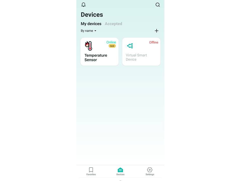
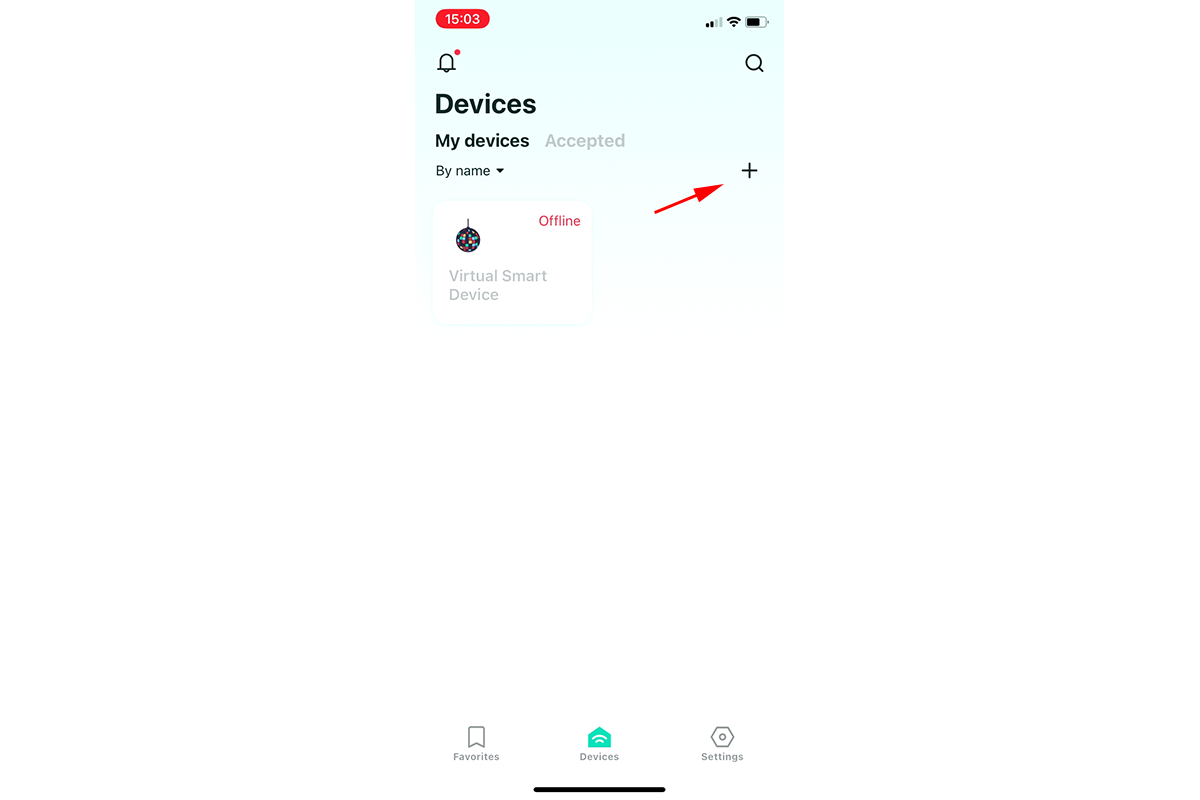
- Go back to the mobile app, click the “Add Device” button on the “Devices” screen and the pairing procedure will start.

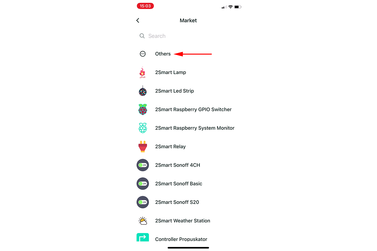
- Select “Others” from the list of available devices to bind to the application. Then click “Continue”.
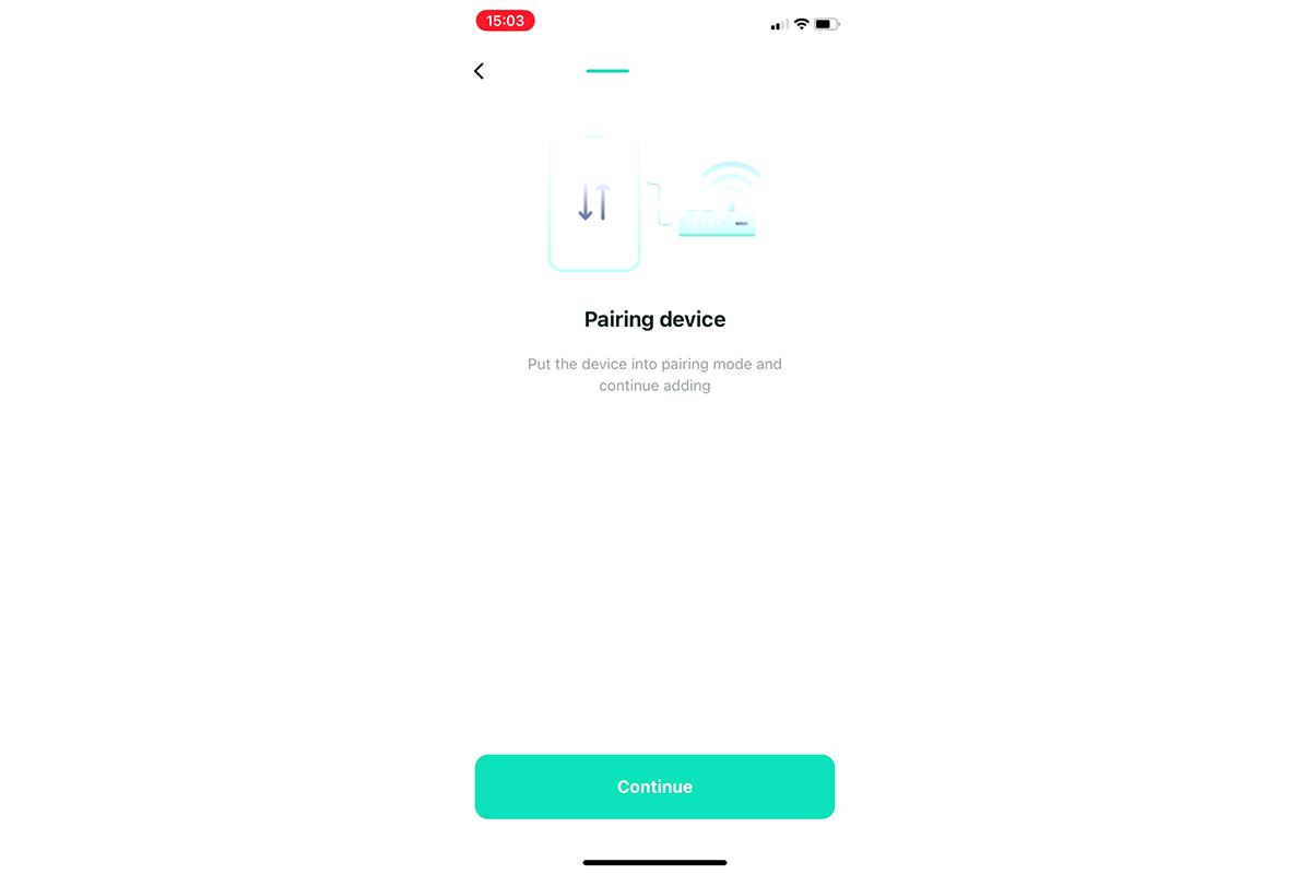
- Specify the data of your Wi-Fi network, which will be sent to the device to connect to the Internet.
- After uploading Production firmware, the microcontroller will have access point mode with a name that meets the name of your device on the platform. Connect to this network in the next step.
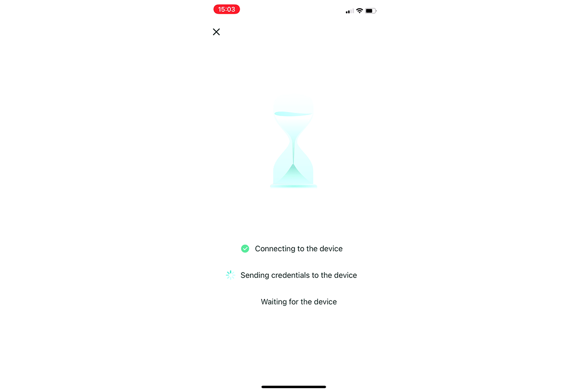
- Wait for the pairing procedure to complete.
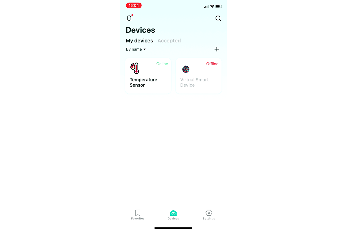
- Your temperature sensor is now displayed on the Devices screen. Make sure you can control it from your smartphone. Wait until the history of temperature and humidity readings appears and check the status of the corresponding graphs.


That’s all! In just 30 minutes, we created a useful IoT device that can be used on a daily basis. If necessary, the temperature and humidity sensor can be placed on a printed circuit board, as well as printed out the device body on a 3D printer. By placing it in a room or any other premises, you can control temperature and humidity from anywhere with Internet access.
Don't forget to share this post!
Read Next


Let’s dive into your case
Share with us your business idea and expectations about the software or additional services.
