
Table of contents:
In the previous article, we described how to make an addressable LED strip controller and write firmware based on the 2Smart Cloud SDK. This article will show you how to write a fully compatible firmware for the same controller but based on ESPHome.
Why another article on creating a controller?
Details on how to make an LED strip controller and write firmware for it are here. The first article describes how to create firmware using the SDK of the platform for IoT product development, a powerful tool that we recommend to most vendors.
However, in many cases, ESPHome is a fairly functional tool. Its main advantage is simplicity. Using ESPHome, it will be easier for you to modify the firmware and add new functionality — for example, connect additional sensors and create a smart multitool. This also means that ESPHome is perfect for prototyping, allowing you to save time creating a Proof of Concept.
You can use the firmware configuration provided in this article as part of the code configuration for a more complex device. You can also use the LED strip controller to compare two firmware creation tools for the ESP32 microcontroller: SDK and ESPHome.
What you need to get started
- Controller. You can find a list of components and a description of the assembly of the device in the previous article.
- Address LED strip.
- Power supply.
- USB-micro-USB cable for flashing.
What will you get
Using ESPHome to create the firmware for an IoT device, with 2Smart, you get a complete product suitable for going to market. Each device with ESPHome-based firmware can be linked to the mobile application using standard pairing. At the same time, the end user specifies the credentials of their Wi-Fi network during pairing; they do not need to be embedded in the firmware code as when using ESPHome on native platforms.
The 2Smart Cloud mobile application, in addition to managing the device using widgets in its interface, provides the following additional features:
- control via Siri and Google Assistant voice commands,
- control via a phone call,
- control via the Telegram bot,
- automation using shortcuts if you have an iOS device,
- sharing in a mobile app or through a browser.
In addition, you can deploy the advanced open-source home automation system 2Smart Standalone and include a device with ESPHome-based firmware in your ecosystem of smart home devices. Such a device can be completely autonomous or combine the advantages of an automation platform with its flexible scenarios and a cloud platform with its ability to control devices remotely from anywhere in the world.
Creating an ESPHome-based controller firmware
- Log in to the vendor account – https://cloud.2smart.com/.
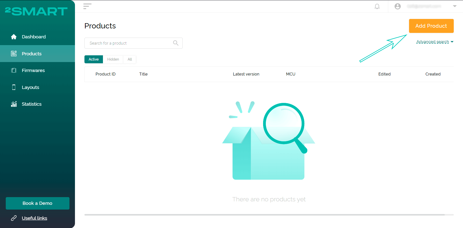
- On the “Products” page, click “Add Product” (the similar button on the Dashboard screen launches a step-by-step assistant – the sequence of steps in the instructions below may vary slightly).

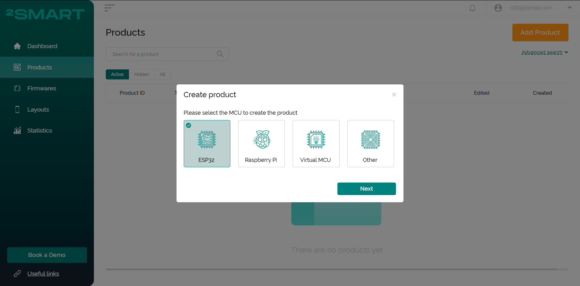
- Select the microcontroller – ESP32.
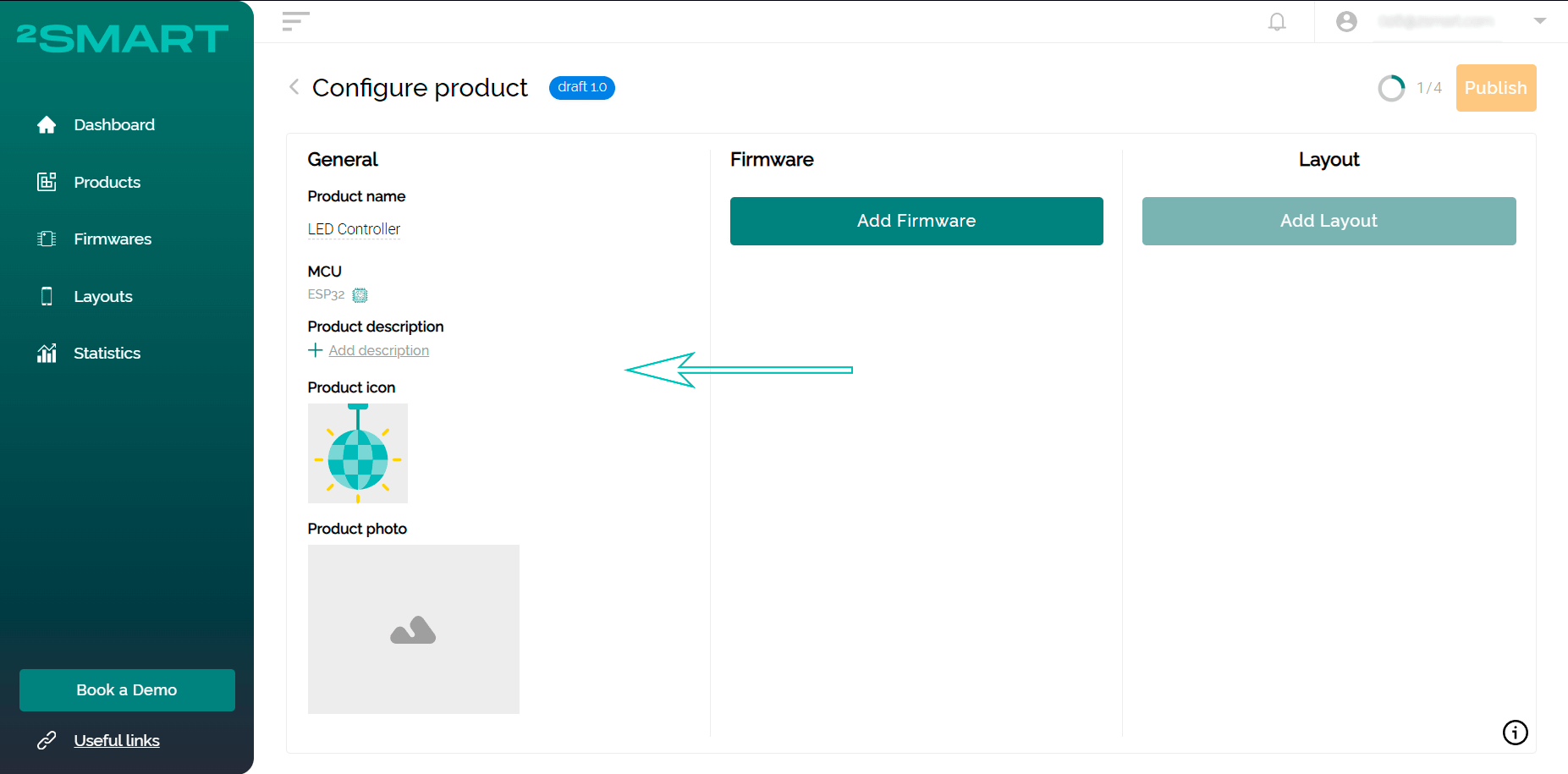
- Add the device name and icon – they will be displayed in the 2SmartCloud mobile app.
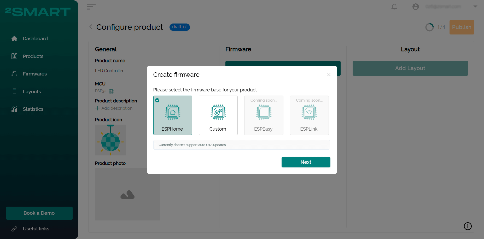
- Click “Add Firmware” and select the ESPHome base.
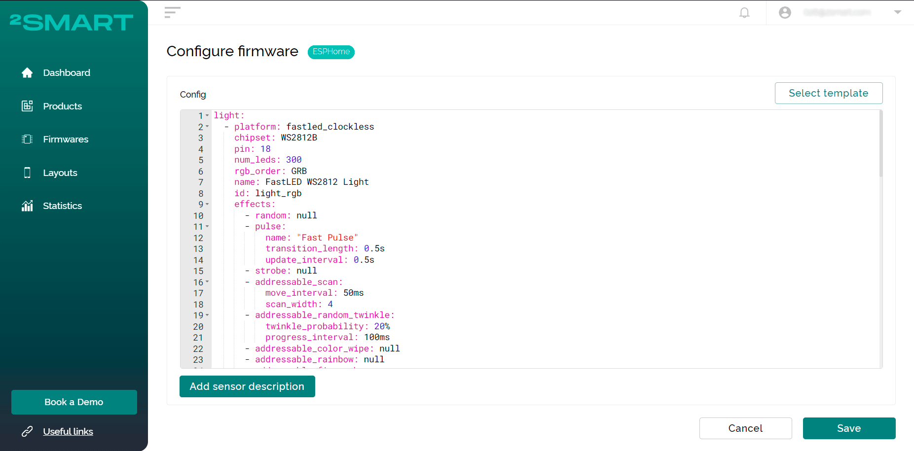
- Paste the YAML configuration for the controller into a new window. Documentation and ready-made examples for ESPHome will help you write it. We used such sources:
- platform for controlling RGB components – https://esphome.io/components/light/fastled.html;
- a library of standard effects and instructions for writing your own – https://esphome.io/components/light/index.html#light-effects.
After selecting the appropriate lines of config, we added controller effects and included support for the Reset button and Wi-Fi signal sensor in the firmware.
Full configuration from our example:
light:
  - platform: fastled_clockless
    chipset: WS2812B
    pin: 18
    num_leds: 300
    rgb_order: GRB
    name: FastLED WS2812 Light
    id: light_rgb
    effects:
      - random: null
      - pulse:
          name: "Fast Pulse"
          transition_length: 0.5s
          update_interval: 0.5s
      - strobe: null
      - addressable_scan:
          move_interval: 50ms
          scan_width: 4
      - addressable_random_twinkle:
          twinkle_probability: 20%
          progress_interval: 100ms
      - addressable_color_wipe: null
      - addressable_rainbow: null
      - addressable_fireworks:
          name: Fireworks Effect With Custom Values
          update_interval: 32ms
          spark_probability: 10%
          use_random_color: false
          fade_out_rate: 120
binary_sensor:
  - platform: gpio
    id: led_switch
    pin:
      number: GPIO5
      mode: INPUT_PULLUP
      inverted: true
    name: Led switch
    on_click:
      then:
        - light.toggle: light_rgb
  - platform: gpio
    id: change_effect
    pin:
      number: GPIO4
      mode: INPUT_PULLUP
      inverted: true
    name: Change effect
    on_click:
      then:
        - lambda: !<!lambda> |-
            uint32_t total = id(light_rgb)->get_effects().size();
            uint32_t curr_idx = 0;
            uint32_t i = 0;
            std::string curr_effect = id(light_rgb)->get_effect_name();
            auto call = id(light_rgb)->turn_on();

            // set first effect in list
            if (strcasecmp(curr_effect.c_str(), "none") == 0) {
              call.set_effect(1);
              call.perform();

              return;
            }

            for (auto *effect : id(light_rgb)->get_effects()) {
              i++;
              if (strcasecmp(effect->get_name().c_str(), curr_effect.c_str()) == 0)
                curr_idx = i;
            }

            if (curr_idx == total) {
              call.set_effect(0);
            } else {
              call.set_effect(curr_idx + 1);
            }

            call.perform();
  - platform: reset_sensor
    pin:
      number: GPIO0
      mode: INPUT_PULLUP
      inverted: true
    name: Reset button
    filters:
      - delayed_on: 1s
sensor:
  - platform: wifi_signal
    name: WiFi1 Signal
    update_interval: 30s
    id: wifi_config
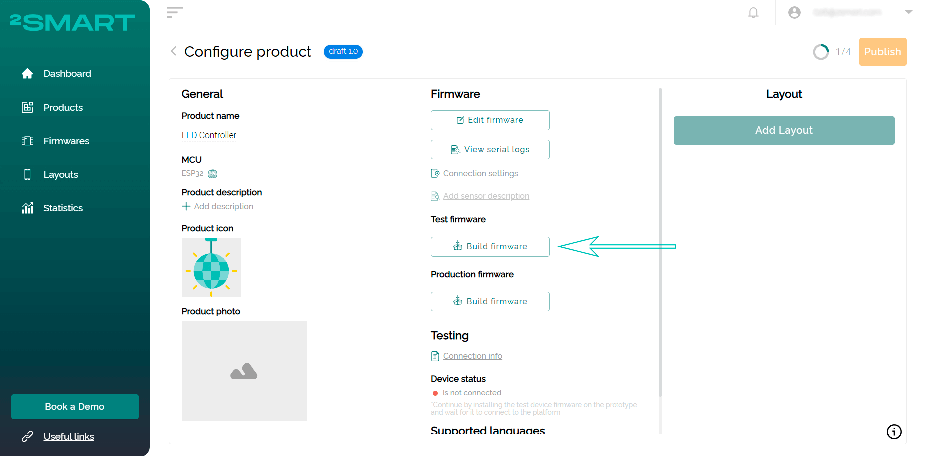
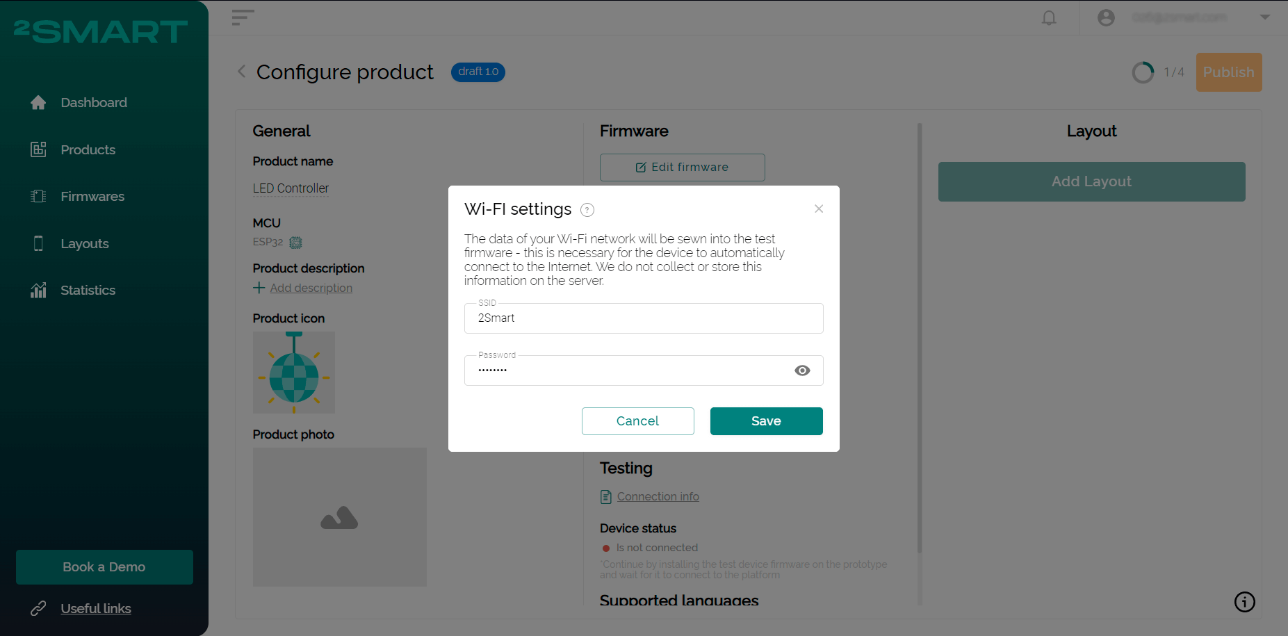
- Save the config. On the product screen, click “Build Firmware” for the test device. Enter the credentials of your Wi-Fi network – they will be transmitted to the device in the test firmware code for a quick Internet connection.
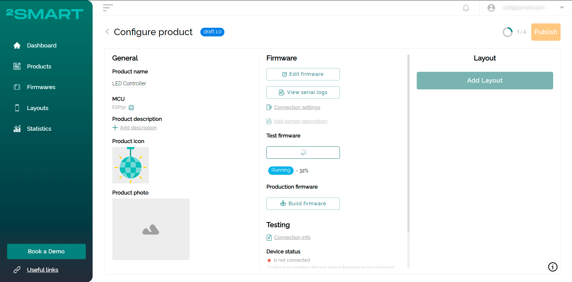
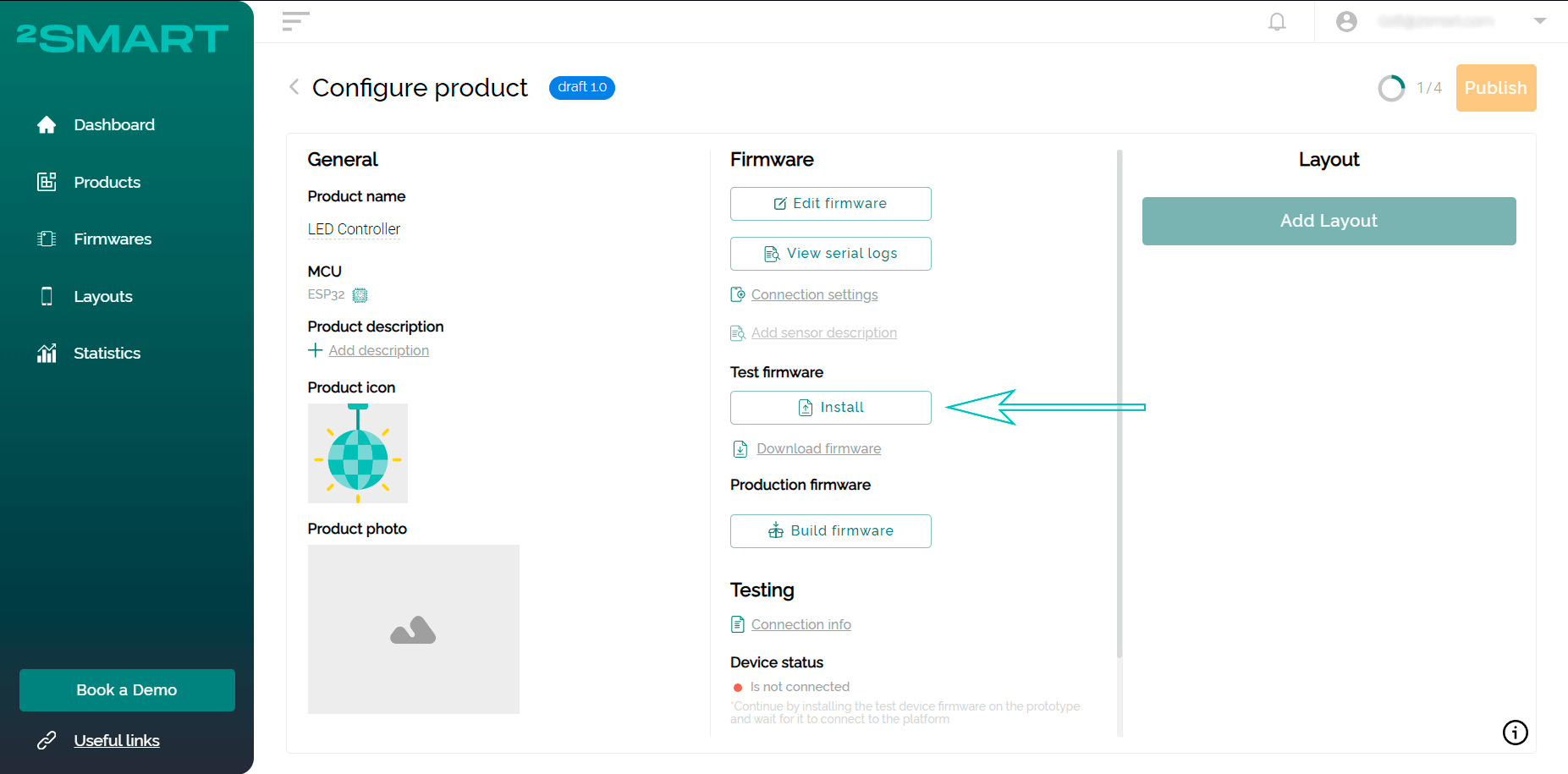
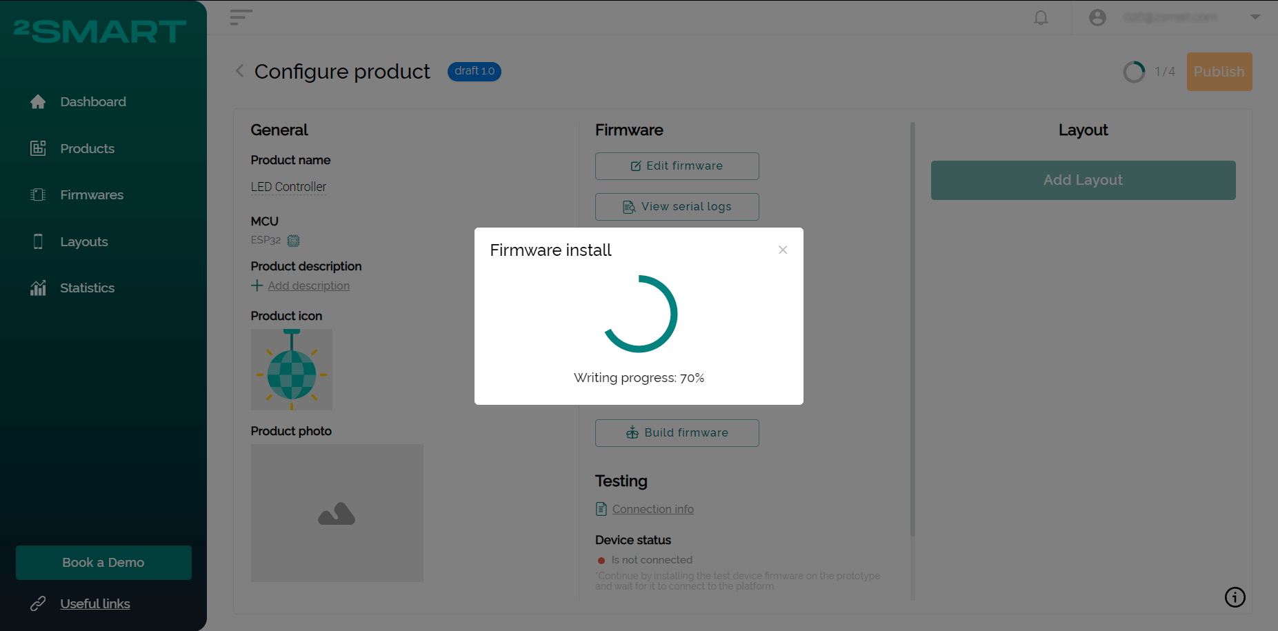
- Wait until the firmware building is completed. Connect the controller to the computer using a USB cable and click “Install” to flash it with test firmware. Use the instructions for installing firmware on a microcontroller using a browser if you have any difficulties.
Attention! Disconnect the LED strip from the controller before proceeding with the flashing!
- If installing the firmware via a browser is not possible, click the “Download Firmware” link and save the ZIP archive on your computer.
Unpack the downloaded archive, enter the folder with the received files, and read the instructions for the flashing in the readme.md file.
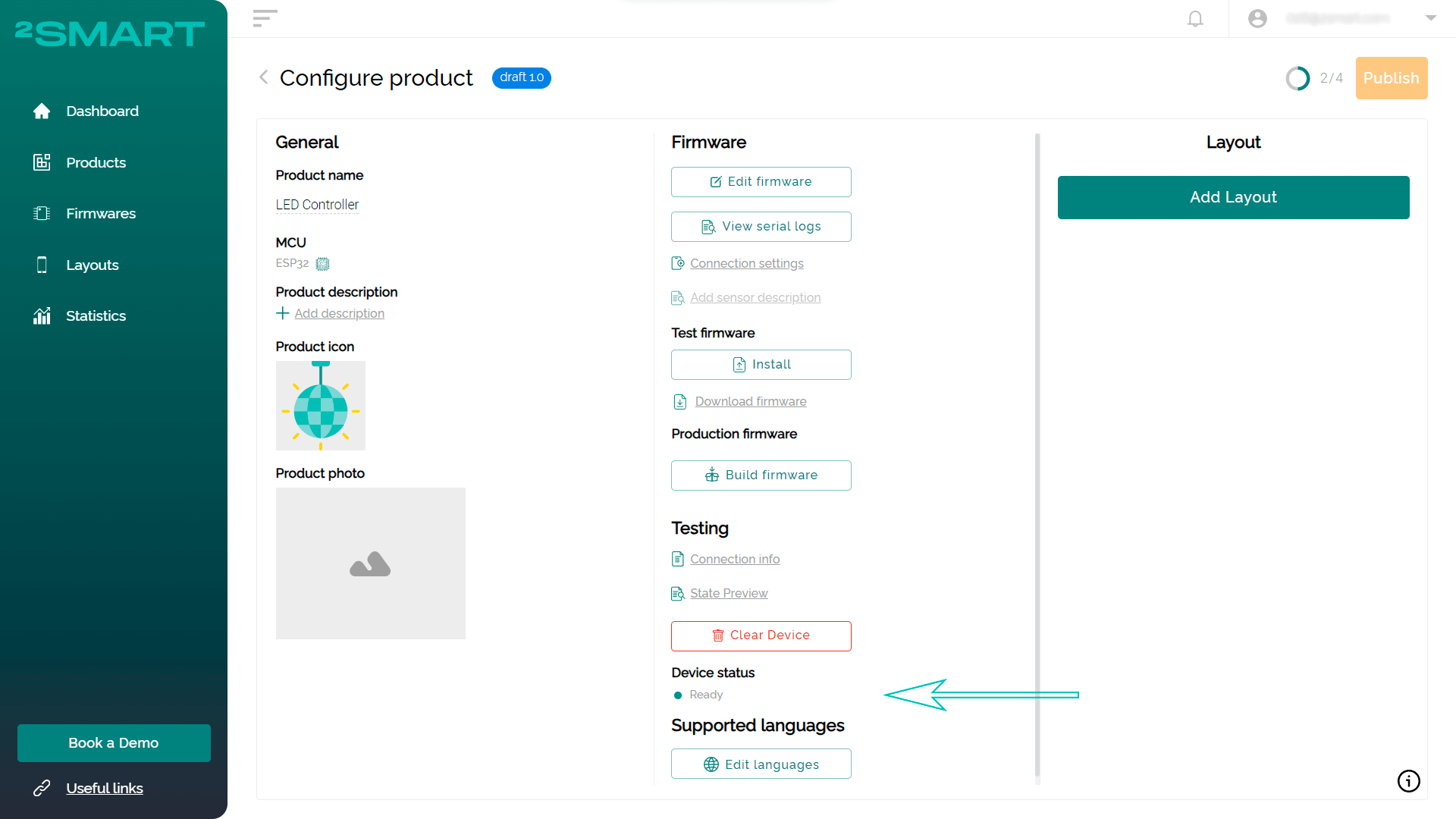
You can flash the device using Mac OS, Linux, and Windows devices. - After completing the firmware installation process, return to the platform – the device will connect to it automatically. The successful connection is indicated by a green indicator and the Ready status in the “Device status” field.

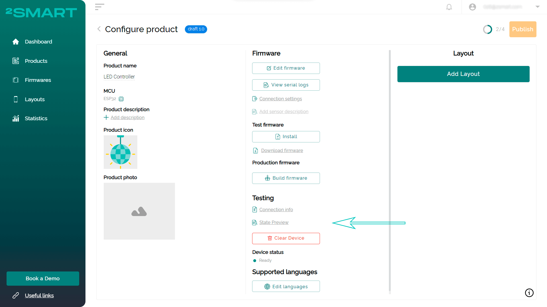
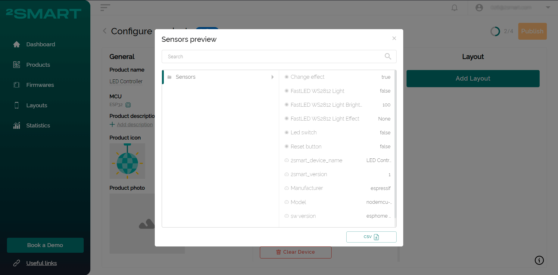
- Click “State Preview” to see all device sensors’ data.
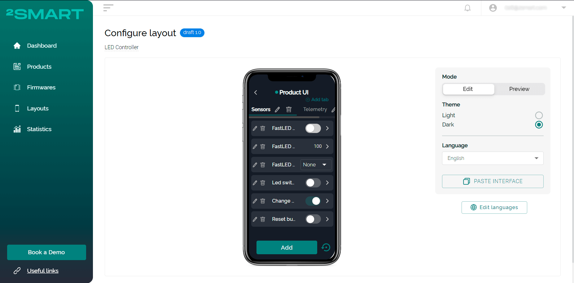
- Click “Add Layout” to open the mobile application emulator.
Let’s collaborate
We’re empower your business with our technology expertise
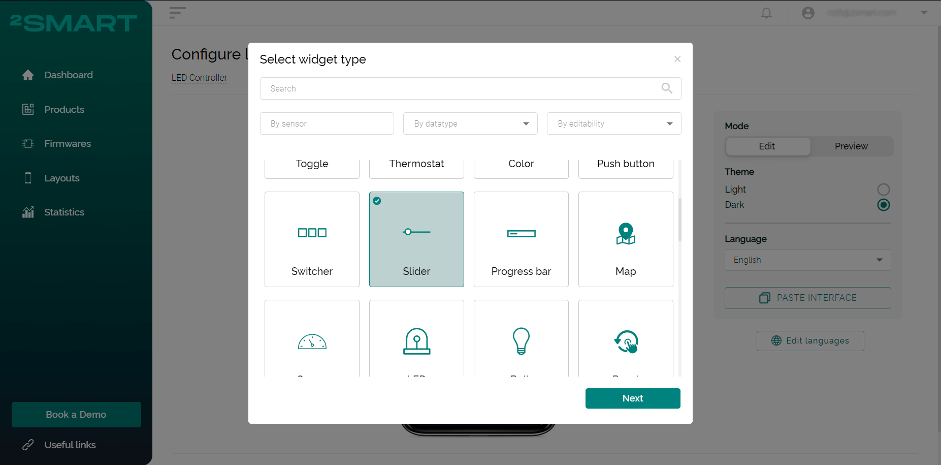
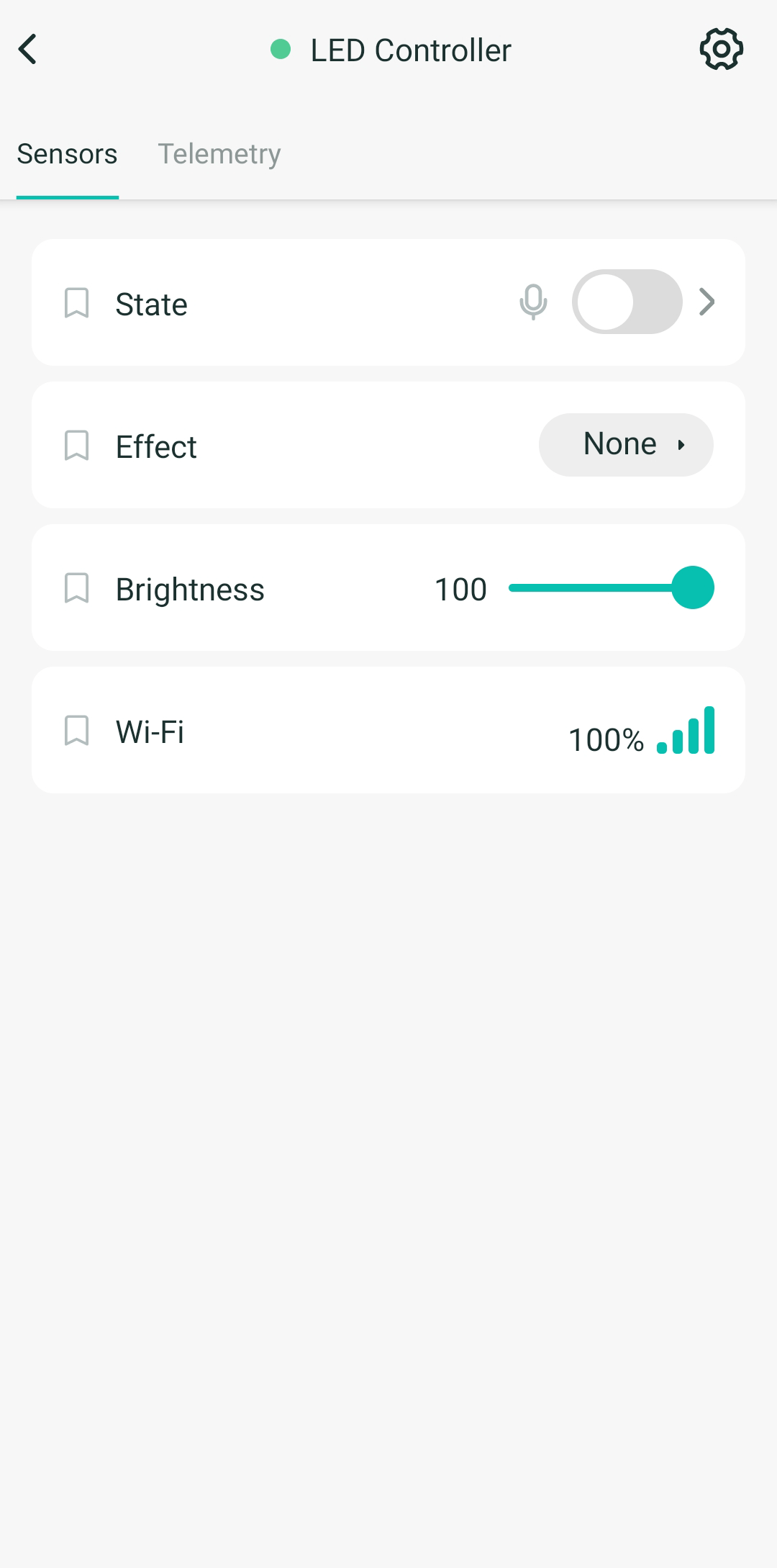
- Appropriate widgets are automatically created for all sensors on your device. You can customize the appearance of the application as you like, including choosing other types of widgets than the default ones. You can also set a convenient order of widgets on the screen.
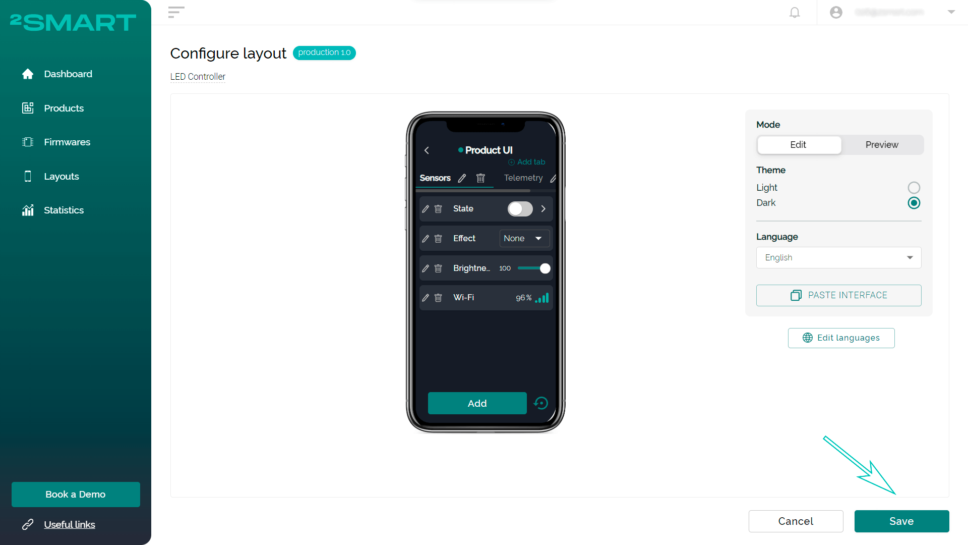
- Please note – you can already control the device from the computer screen at this stage. After completing the interface configuration, click “Save”.
- Launch the 2Smart Cloud mobile application on your smartphone; you have probably already used it to connect and control a virtual lamp. Log in with the same username and password that you used to register in the developer’s account.
- Your new device is already displayed in the app. Please test the functionality of all widgets.

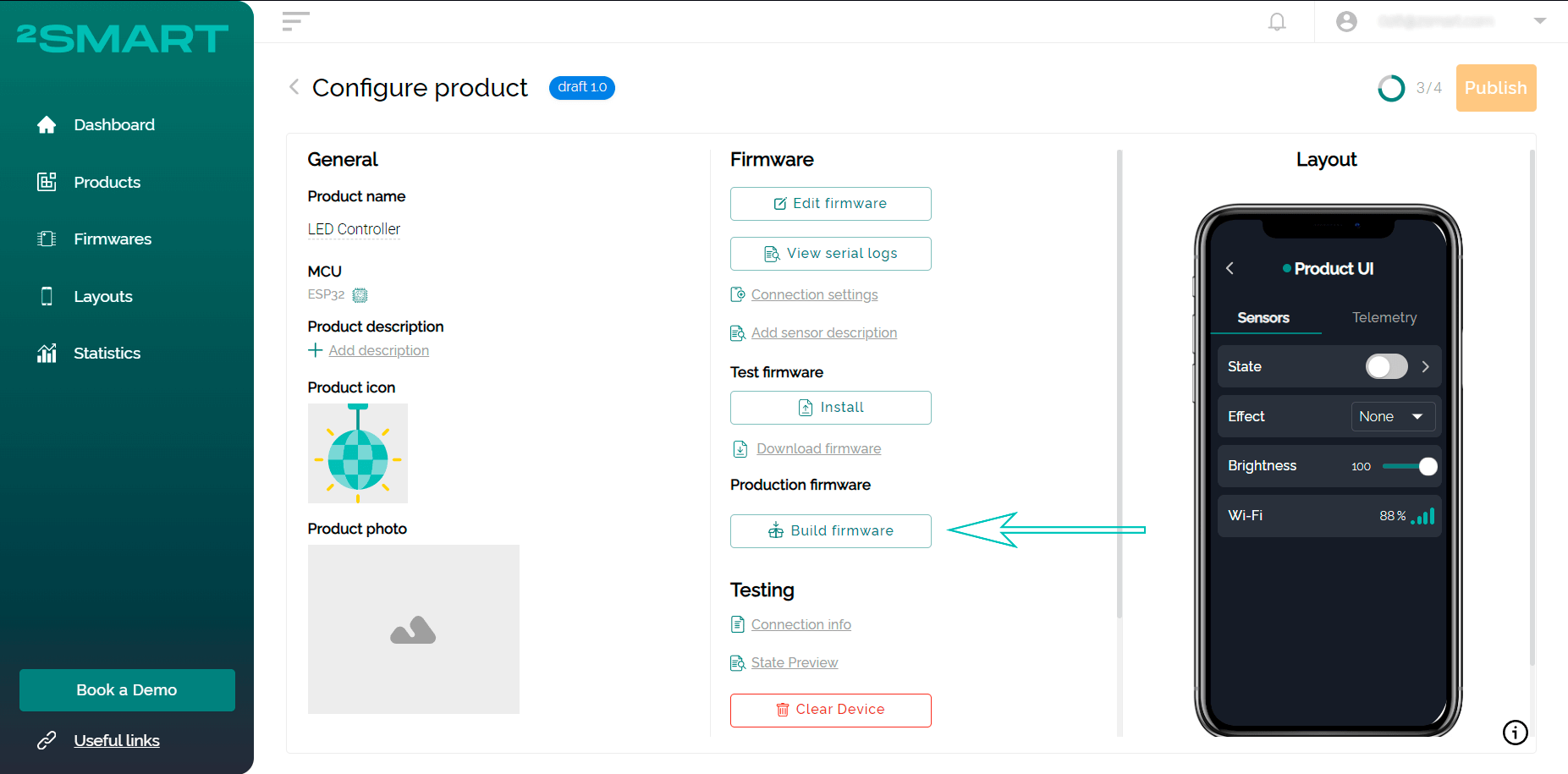
- Return to the platform and click “Build firmware” for the production device. The final version of the firmware will be built, which does not contain the parameters of your Wi-Fi network and other specific lines of code that are necessary for testing the prototype.
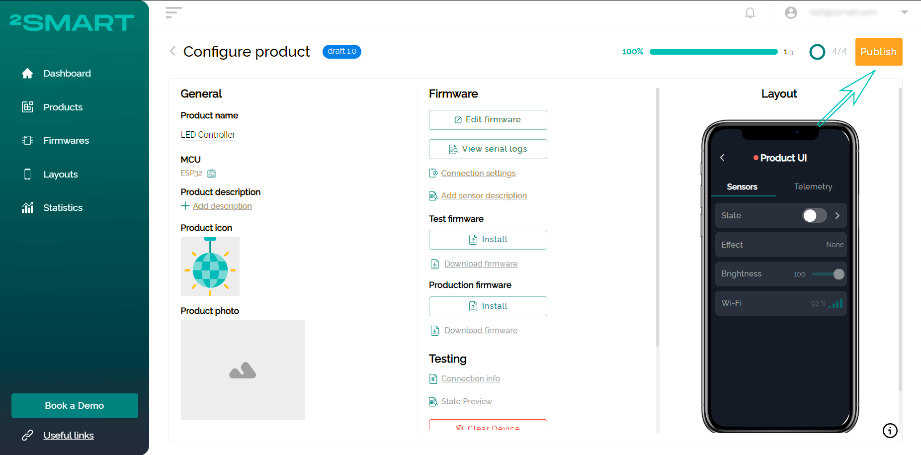
- Click “Publish”, and the product will be available to users for pairing with a mobile device.
- Flash the device with production firmware similar to the test firmware. Do not forget to clear the memory of the microcontroller beforehand.
Attention! Disconnect the LED strip from the controller before proceeding with the flashing!
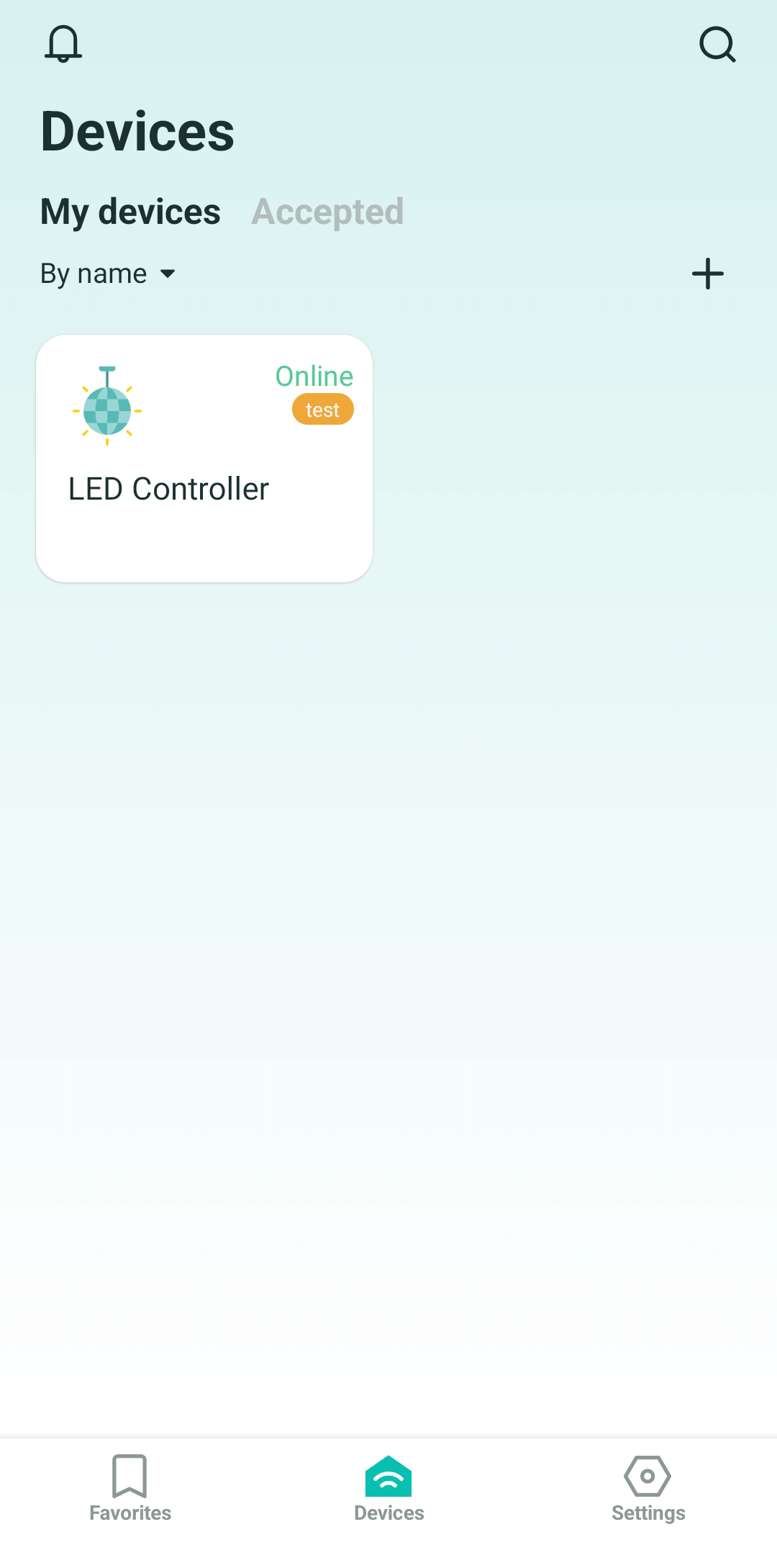
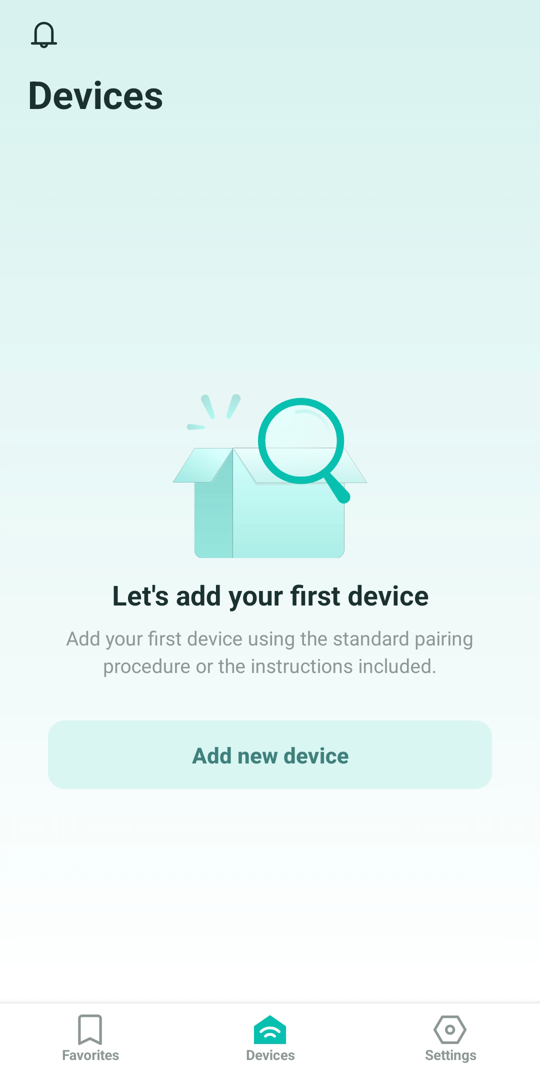
- Return to the mobile application, log in with any credentials as a regular user.
- Click the “Add new device” button on the “Devices” screen – the pairing procedure will start. Refer to the instructions for pairing 2Smart Cloud devices, keeping in mind the following:
- in step 3, select “Others” in the built-in market,
- in step 8, look for a Wi-Fi network with the same name that you gave to your device in the developer’s account; you do not need to enter a password.
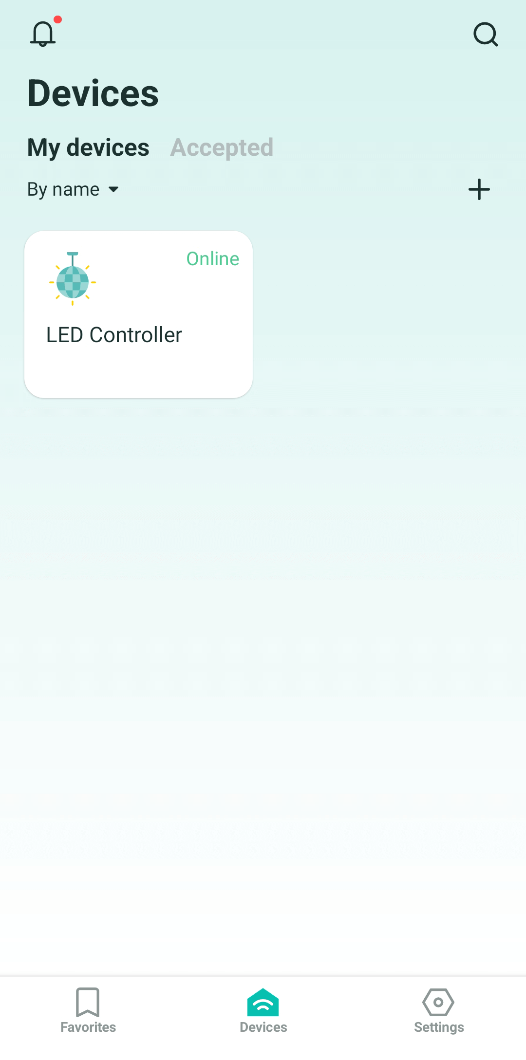
- Now your LED strip controller is displayed on the Devices screen. Make sure you can control it from your smartphone screen.
That’s it! We have created a LED strip controller without programming and using assembler programs. The firmware code for ESPHome was written according to the documentation for this base. In fact, we just took ready-made examples and used them on our device.
Simplicity is the main advantage of ESPHome. Therefore, even if you plan to use firmware based on our SDK on production devices, we recommend testing the product using simpler tools. This reduces the time to create an IoT device.
The development of this idea is an LED lighting smart IoT solution where the controller described above controls the LED matrix, which is the basis for a smart lamp with multiple effects.
Don't forget to share this post!
Read Next


Let’s dive into your case
Share with us your business idea and expectations about the software or additional services.
