
Table of contents:
Working on the 2Smart Cloud platform, we have developed several simple IoT devices for testing it. An ESP32-based Wi-Fi controller for addressable LED strips is one of these products. The device is controlled via a mobile application as well as other methods such as voice commands, a phone call, and a Telegram bot — these controls are available to all users. You can use our project and build a similar device at home. We’ve published the device’s schematic diagram, printed circuit board design, 3D model of the case, and firmware code. Besides this, we’ll show you how to assemble a Wi-Fi LED strip controller, as well as how to add your own effects to the firmware and register the controller as your own product on the platform.
Controller board assembly
All technical materials on creating a controller, including a printed circuit board project, can be found on the 2Smart Cloud GitHub. First, you need to use the Gerber project to order or make your own board.
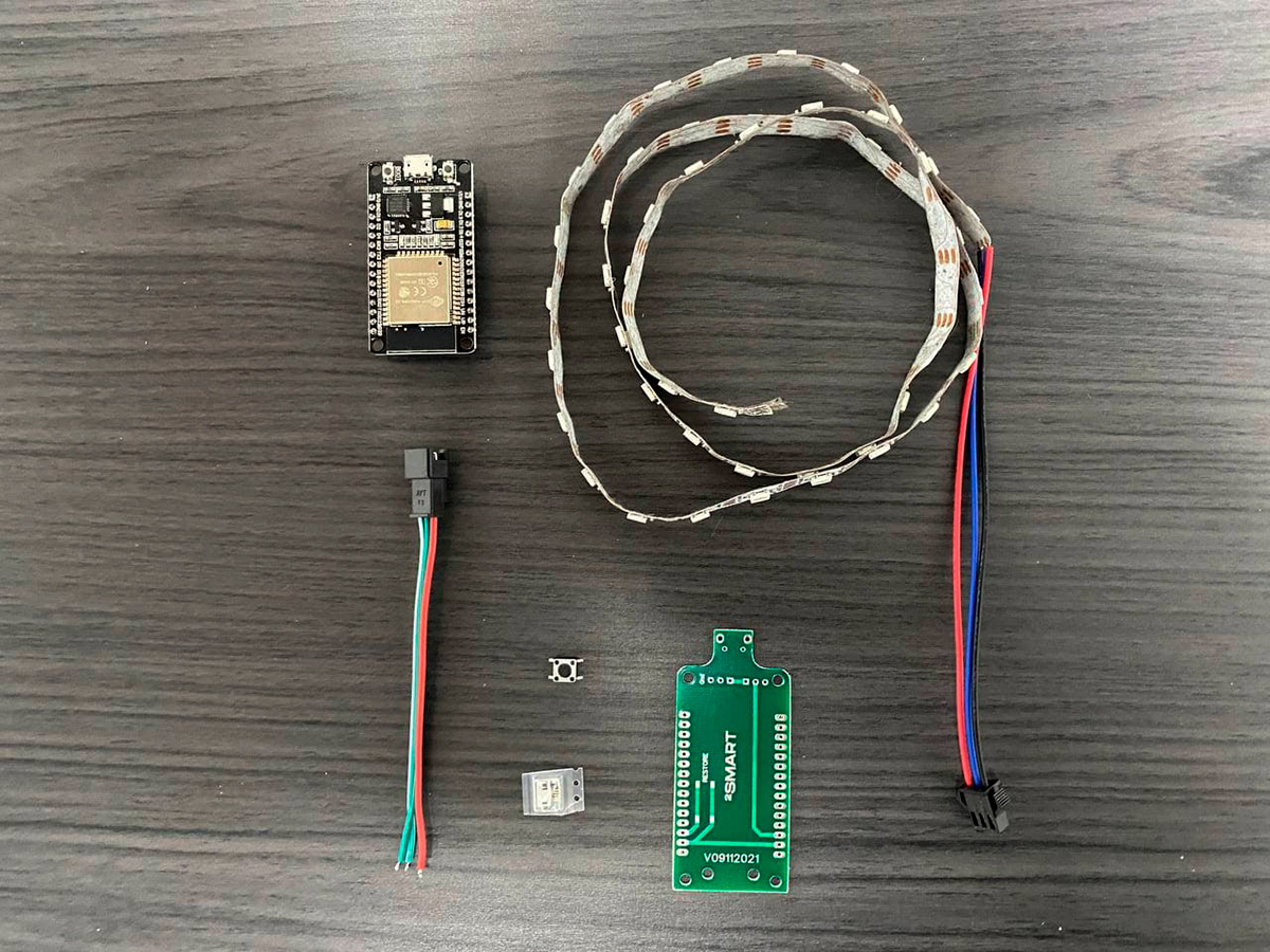
To assemble the controller, you will need the following components:
| ESP32 DevKit board | 1 pc. |
| 5×5 SMD clock button | 1 pc. |
| micro USB connector | 1 pc. |
| JST 3-PIN connector with a wire for connecting the LED strip | 1 pc. |
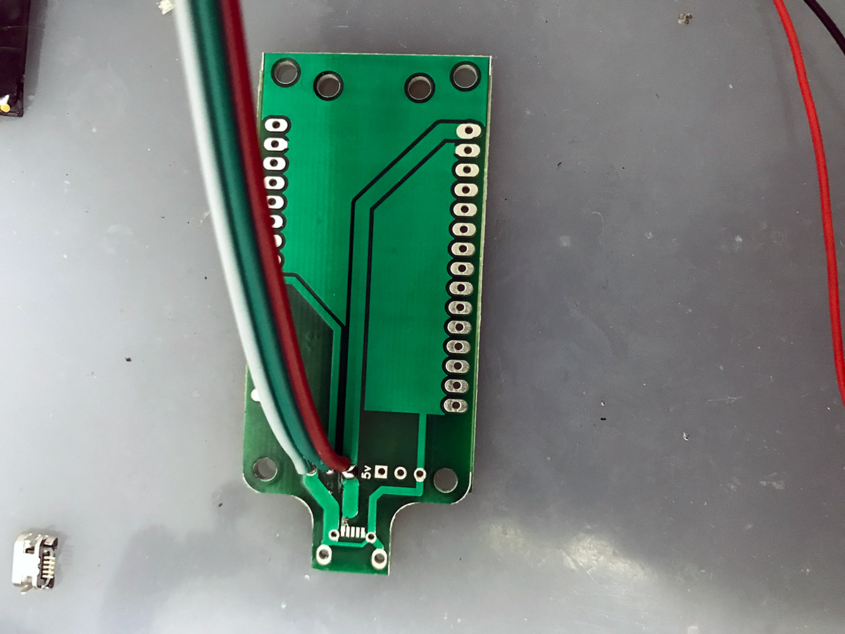
Let’s assemble the controller using these components:
- Solder the LED strip connector.

- Solder the USB port.
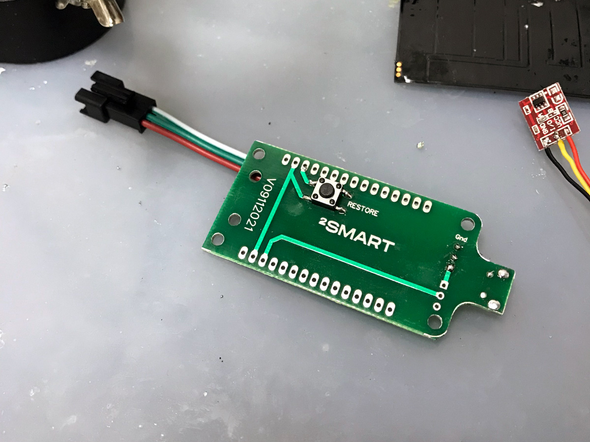
- Solder the button.
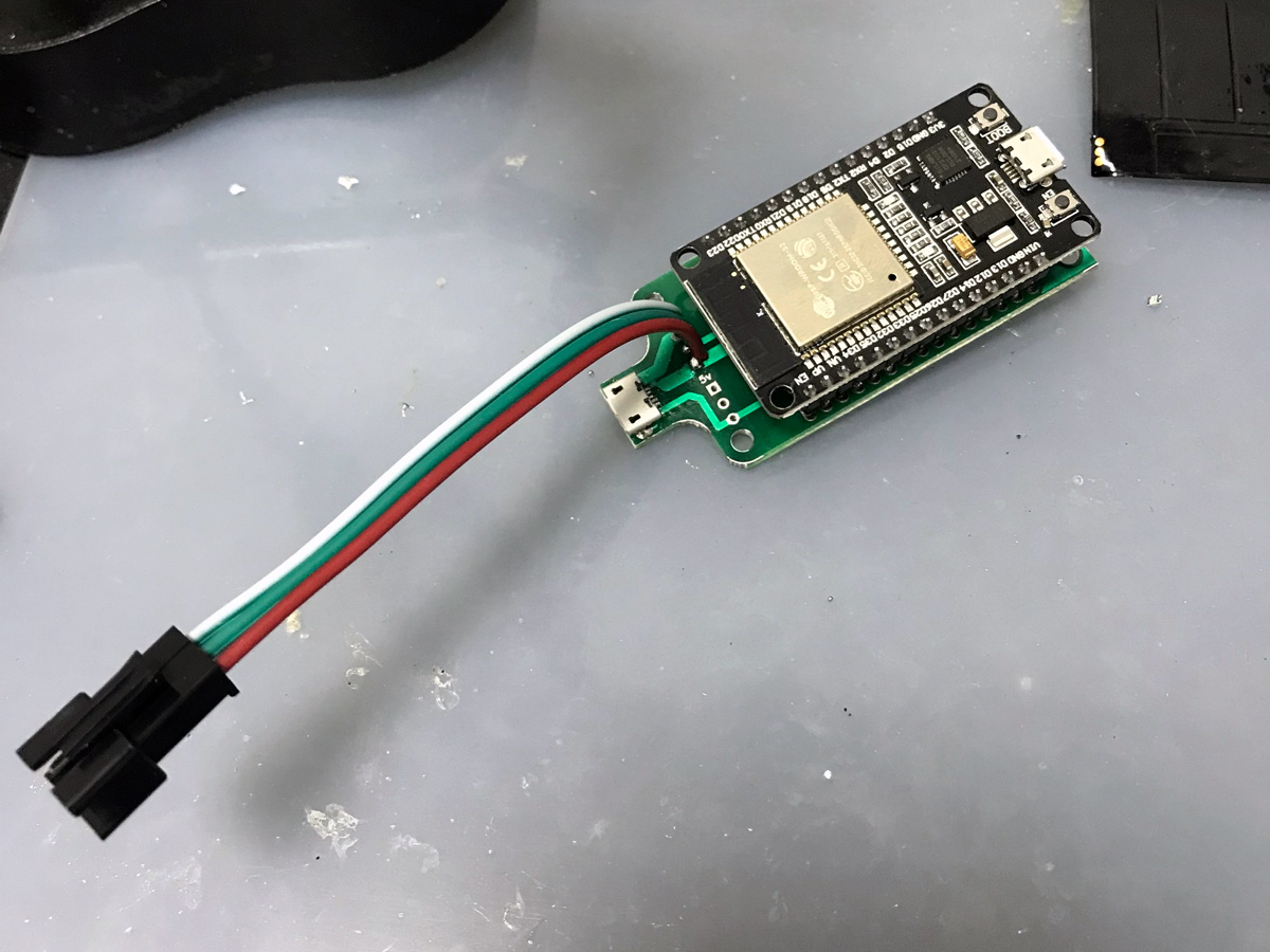
- Solder the microcontroller.
- Connect the LED strip for testing.


Controller firmware
After assembling the device, you just need to flash it and start using it for its intended purpose. There are two possible options at the flashing stage:
- Use the firmware code from GitHub without changes. In this case, you don’t have to register as a 2Smart Cloud vendor. Just pair the assembled and flashed device to the mobile application. This option is similar to buying a ready-made controller in a store – you will be able to use only those modes already in the firmware or will appear in the future after updating. The manufacturer, or vendor, in this option, is the 2Smart Cloud team.
- Get the code from GitHub, specify your product ID and use the controller as your own product. In this case, you can fix and modify the firmware as you like, add new modes, and customize the mobile application’s interface. The vendor in this option is you.
The first option is very simple – you only need to flash the device with a ready-made code and pair it to the mobile application. Firmware instructions are given in the readme file inside the repository.
As for the second option, it requires additional explanations.
Creating a product on the platform and adding a new strip mode to the firmware code
To adapt the ready-made firmware code for yourself and add new controller effects, first of all, you need to create a new product in the 2Smart Cloud developer cabinet:
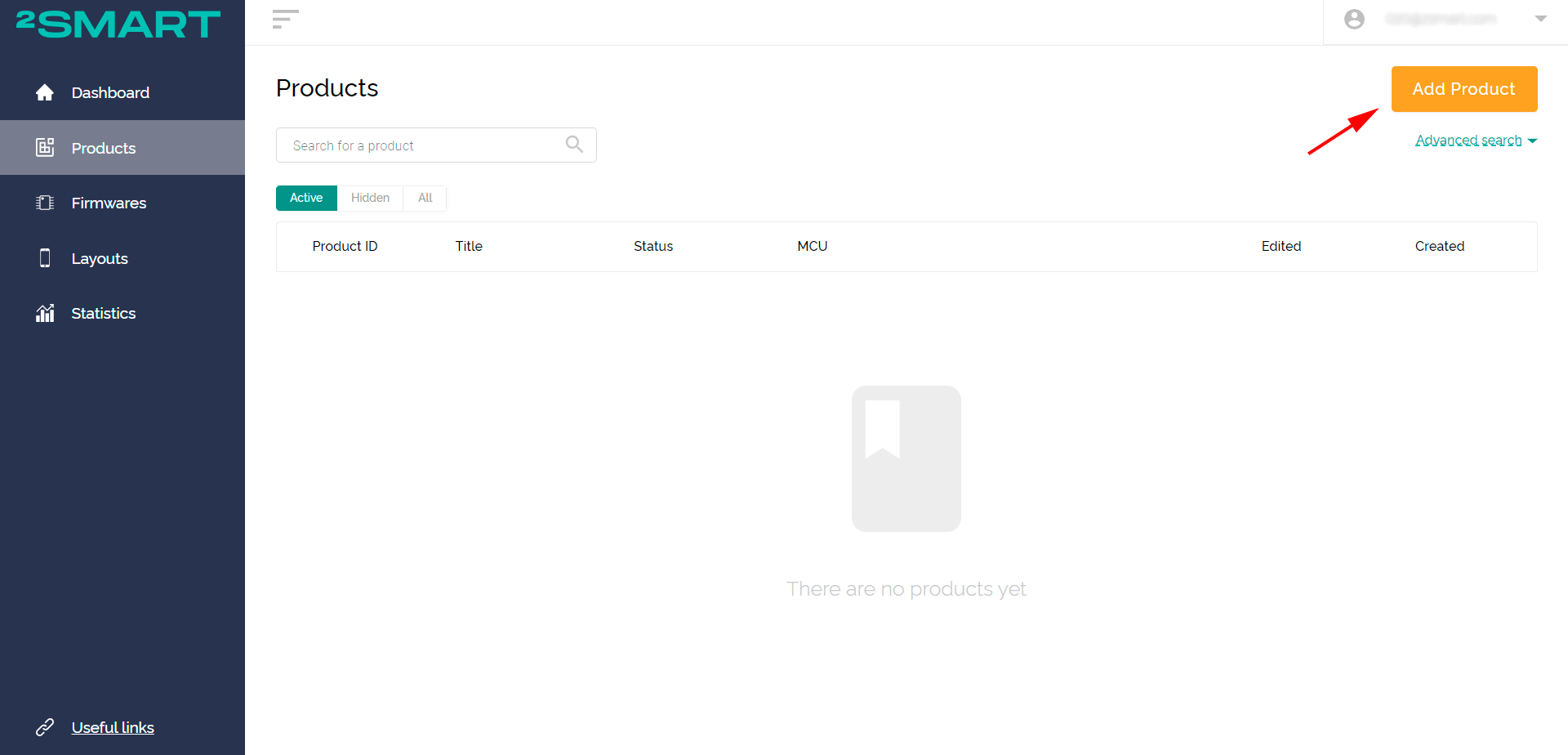
- Go to the “Products” tab and click “Add Product”.

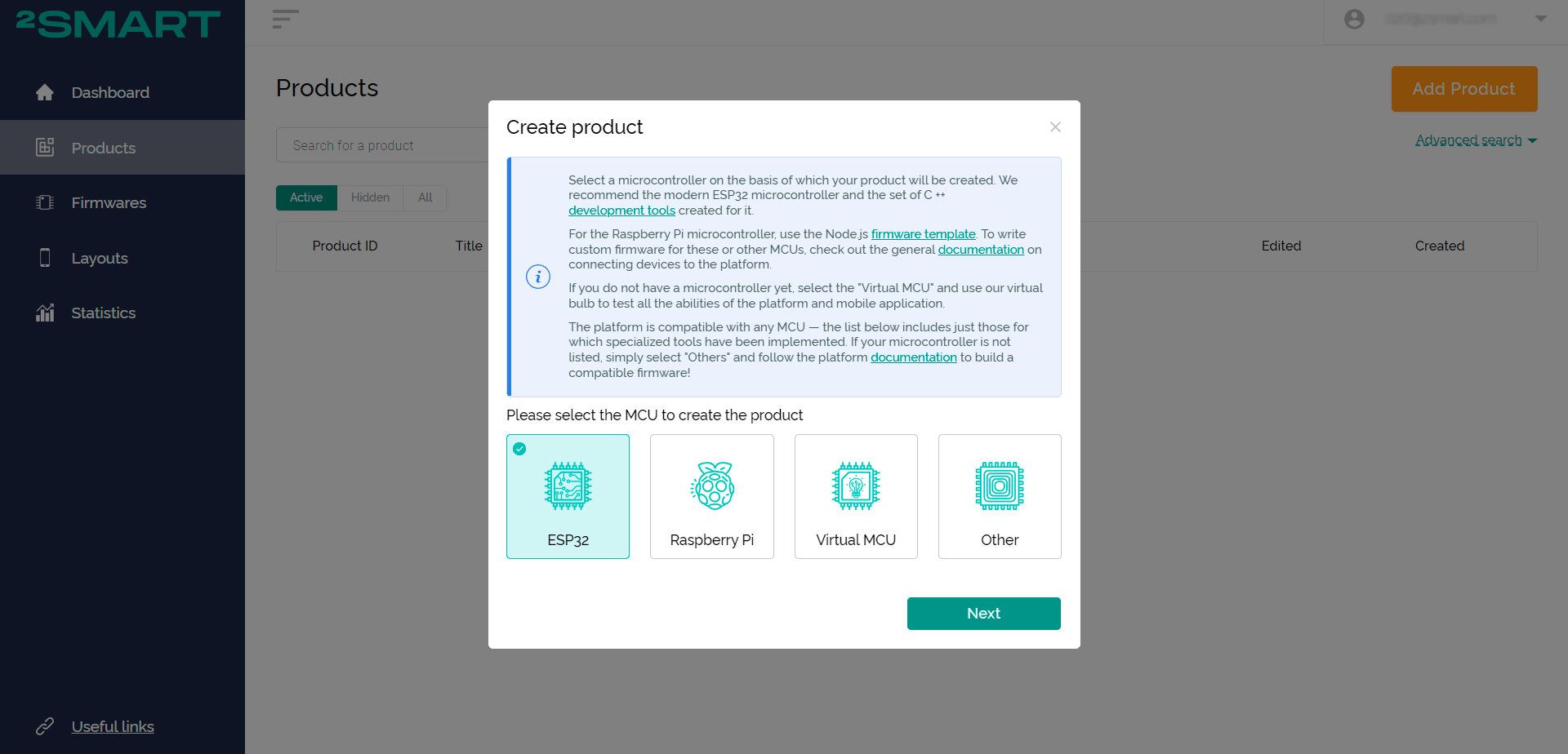
- Select the microcontroller – ESP32.
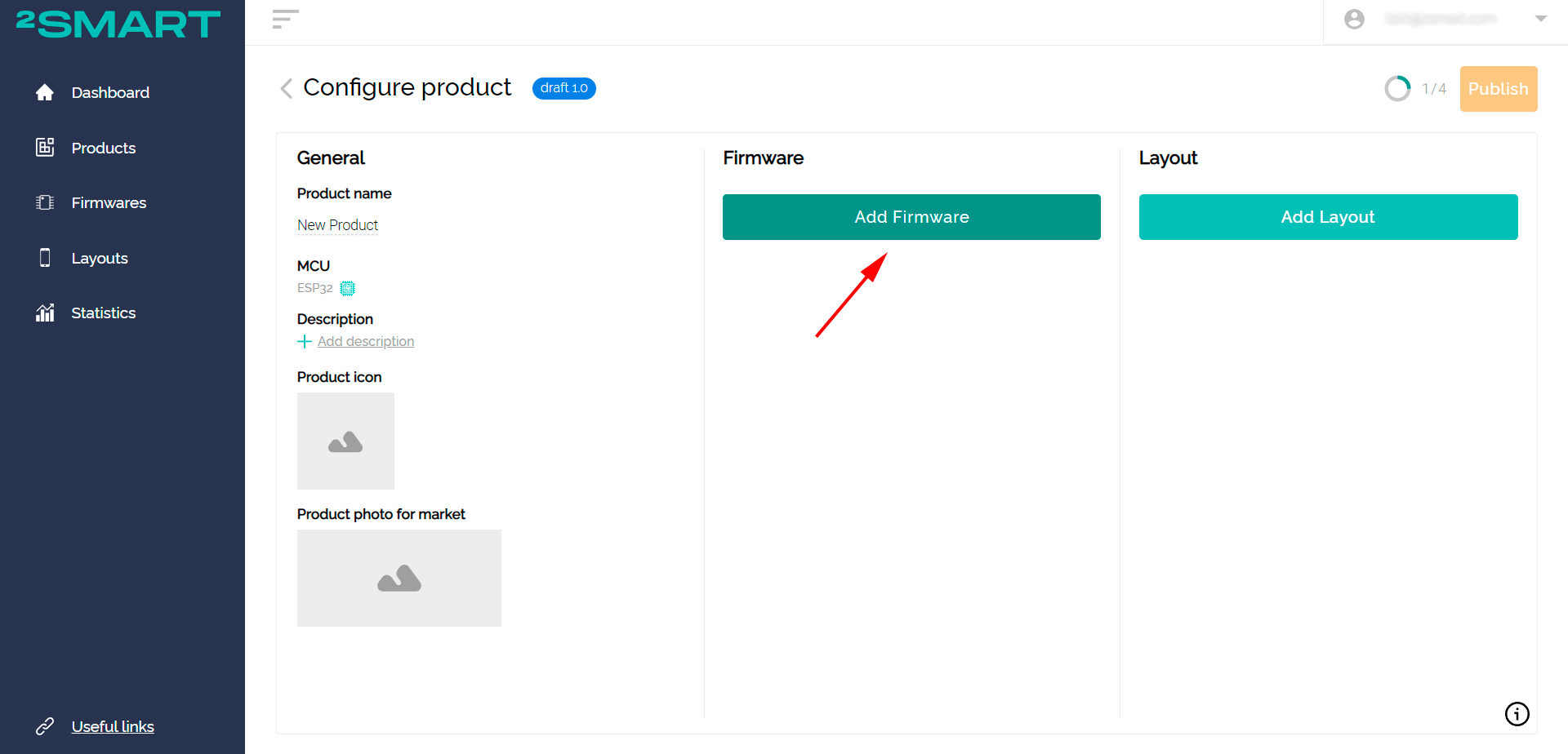
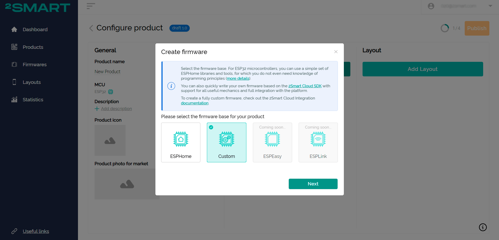
- Click “Add Firmware” and select the Custom option.
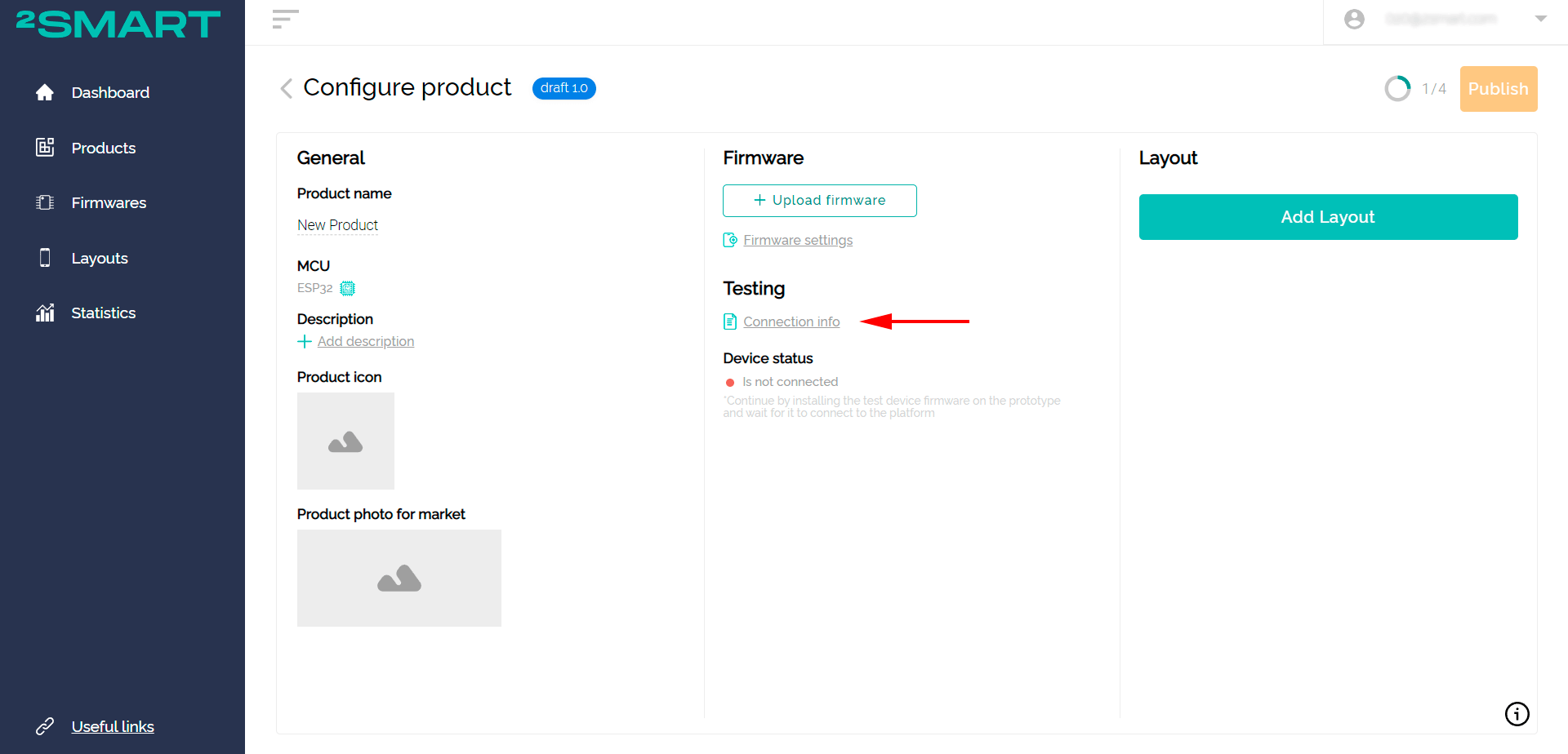
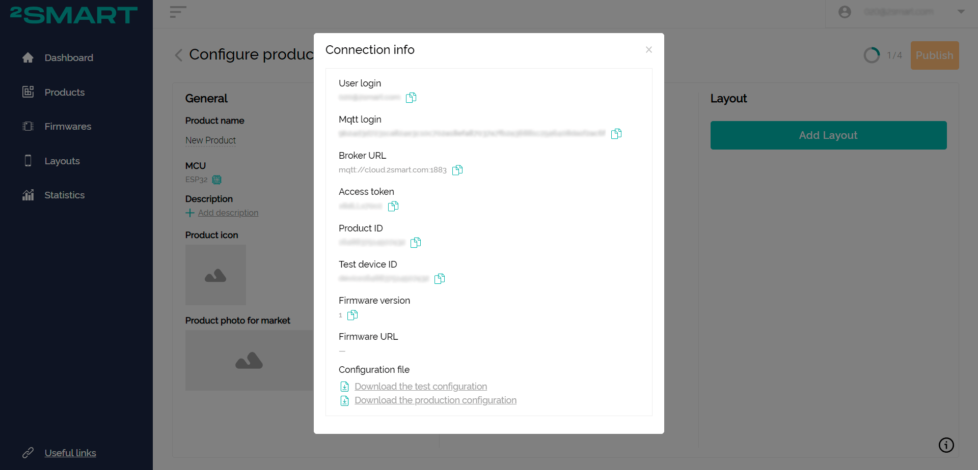
- Click the “Connection Info” link and leave the window with the product connection parameters open.
- Download the LED strip controller project from the repository. Open it in the terminal, and make the necessary changes in a text editor.
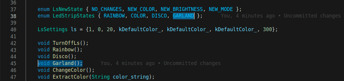
Below we will demonstrate how to modify the firmware, using the example of adding a new mode:- add the effect method to lib/lenta/lenta.h, add the effect name to LedStripStates:

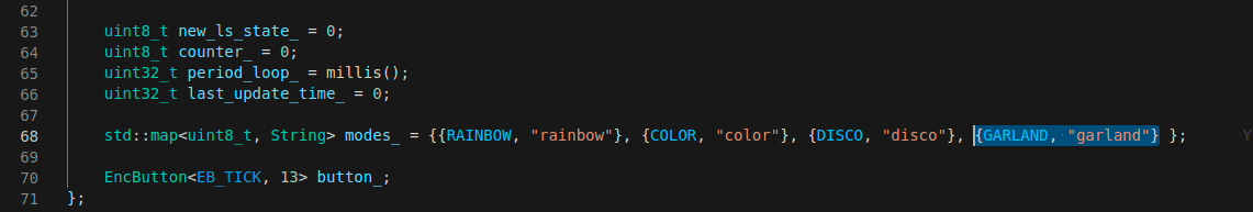
- in modes_, assign the name for the mobile application to the name of the effect:

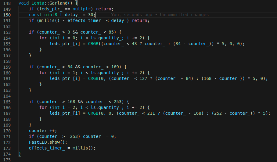
- in lib/lenta/lenta.cpp add the method body with a description of the entire logic of the effect. If necessary, add auxiliary methods.
Attention! Remember that diode lighting is also a mode task., for which you need to use the LEDS.show(); command.

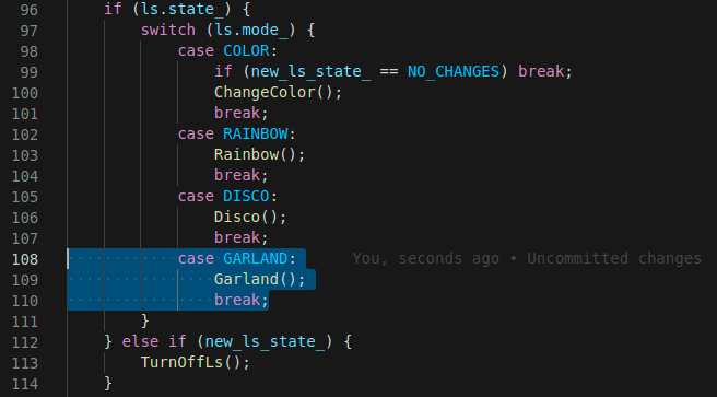
- in HandleCurrentState, add the mode to switch:

- add the effect method to lib/lenta/lenta.h, add the effect name to LedStripStates:
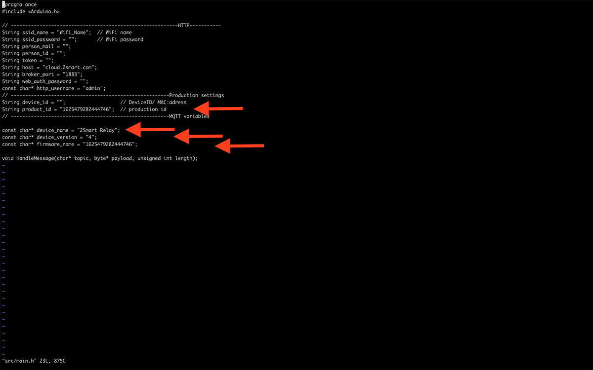
- Open the Firmware/src/main.h file and make the following changes:
- copy the product ID from the “Connection Info” window in the vendor’s account and paste it into the firmwareName and ProductID fields,
- specify the name of your device’s access point instead of the default one in the deviceName area,
- if you create a new product, make sure that its device_version is set to 1.

- Connect the controller to the computer with a USB cable and flash it. Don’t forget to disable the feed first!Use the following commands to install the firmware:
pio run -t uploadfs
pio run -t upload
- After completing the firmware installation, the device activates its Wi-Fi access point. When connecting to it, you will be able to access the controller’s web interface and configure it to connect to the platform:
- link to the access point of the controller – “2Smart Led Strip” (the name can also be changed to your own in the main.h file) and enter the link http://192.168.4.1 in the address bar of the browser to enter the web interface device, use the login and password “admin”,
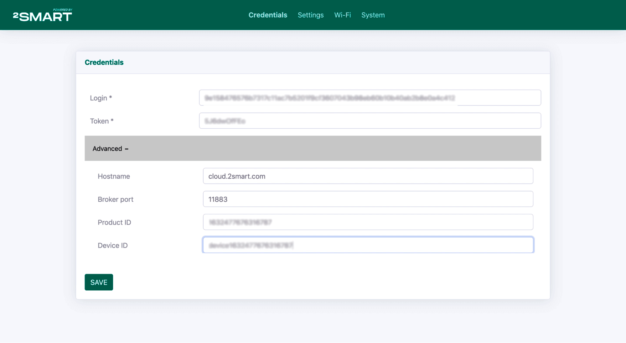
- on the Credentials tab, specify your product parameters from the “Connection Info” window opened in the vendor’s cabinet:
- in the Login field – the value “User login”,
- in the Token field – the value “Access token”,
- in the Hostname field (under the Advanced spoiler), enter the value “cloud.2smart.com ”,
- copy the value “Test device ID” in the Device ID field.

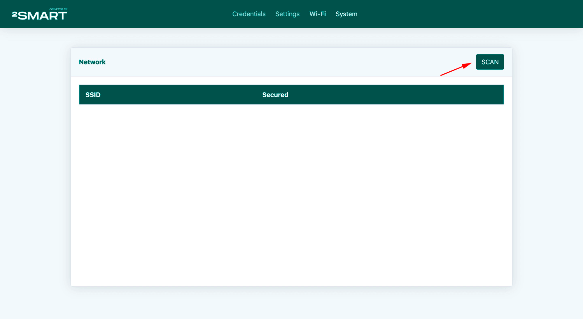
- after filling in all the fields, click Save and go to the Wi-Fi tab of the controller’s web interface. Click Scan to search for available Wi-Fi networks:
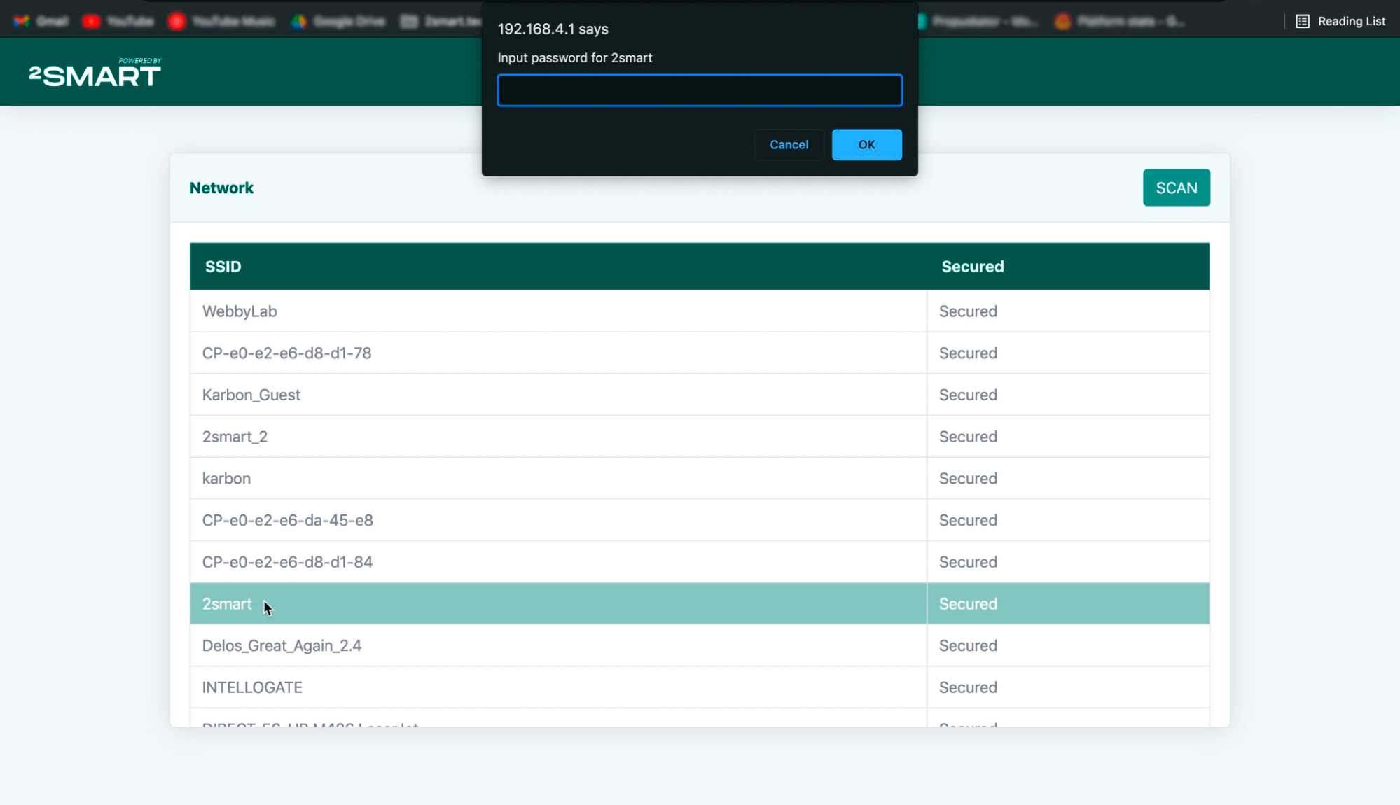
- select your access point from the list of found access points and enter your password:

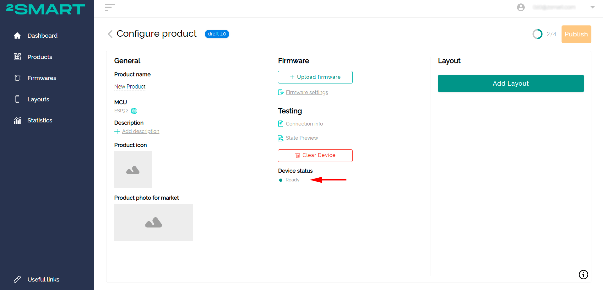
- If all the settings are correct, the device will connect to the platform, and its status will change to Ready.
Let’s collaborate
We’re empower your business with our technology expertise
Setting up and publishing a product
- Click “Add Layout” and customize the appearance of the mobile application. For more information about setting up the interface, see the article about creating a temperature sensor or the series of articles about creating a “smart” Wi-Fi relay.
- Test device control from the application emulator or directly from your smartphone – just log into the application with the same login and password as in the developer’s cabinet.
- After successful testing, the device is ready to be published on the platform. It remains to upload the firmware to the platform server and publish the product.
You can find the finished firmware file in the Firmware/.pio/build/esp32dev/firmware.bin folder (do not forget to enable the display of hidden files in the explorer to find the directory). - Click “Upload firmware” in the vendor’s office and upload the .bin file.
- After uploading the firmware, click “Publish”. After the product is published, it will be available for binding to the mobile application by all users. The standard procedure is enough to pair the device to the mobile application.

Pairing to a mobile device
Method one: without flashing the device
- To pair the controller to the mobile application as a regular user, first reset the device. To do this, hold down the Reset button for 5 seconds until the LED on the MCU board starts blinking at 3 second intervals.
- Go back to the mobile app, log in with any credentials.
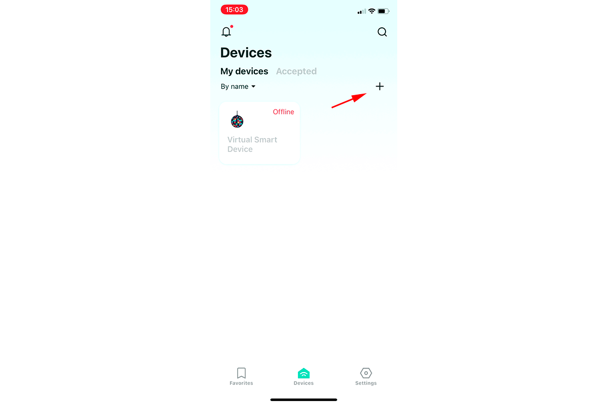
- Click the “Add new device” button on the “Devices” screen, and the pairing will start.

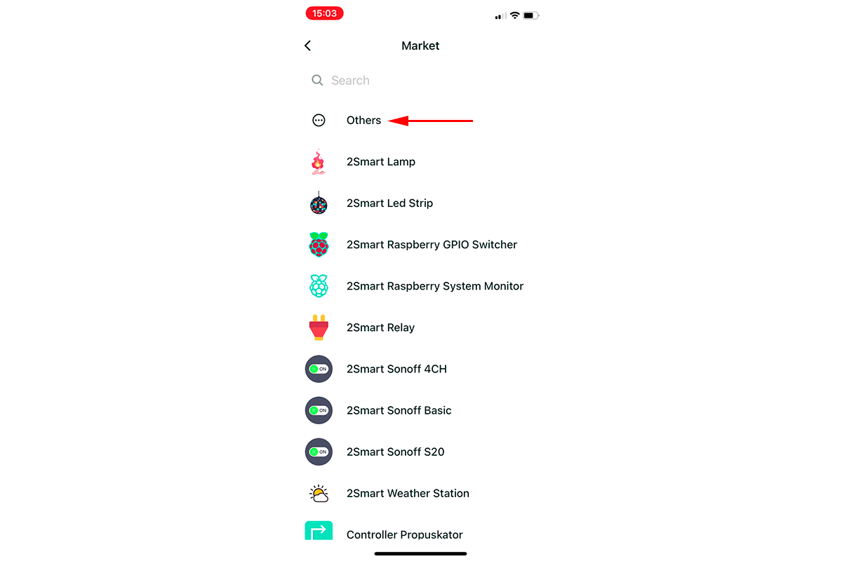
- Select “Others” from the list of devices available for pairing. Then click “Continue”.
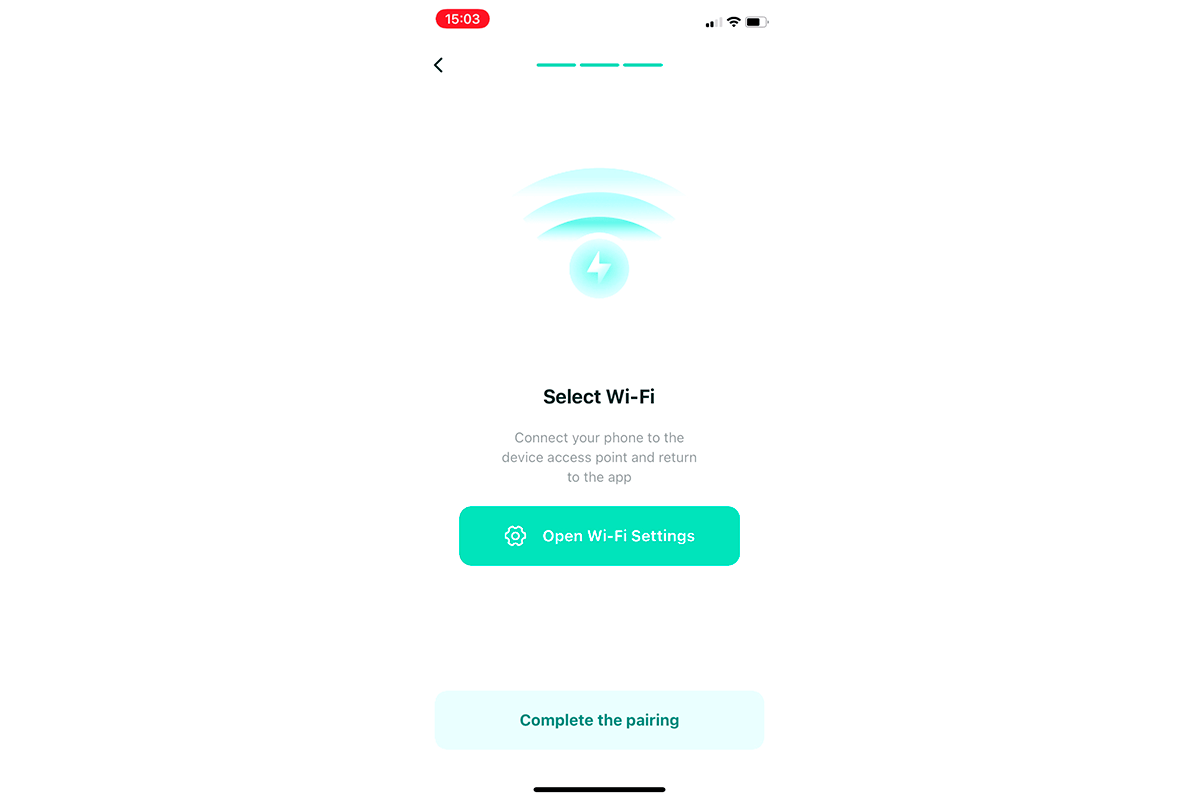
- Enter the credentials of your Wi-Fi network to transfer it to the device for connecting with the Internet.
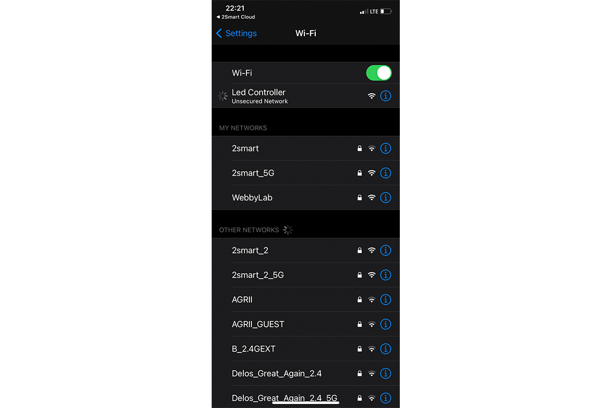
- Connect to the Wi-Fi hotspot of the controller.
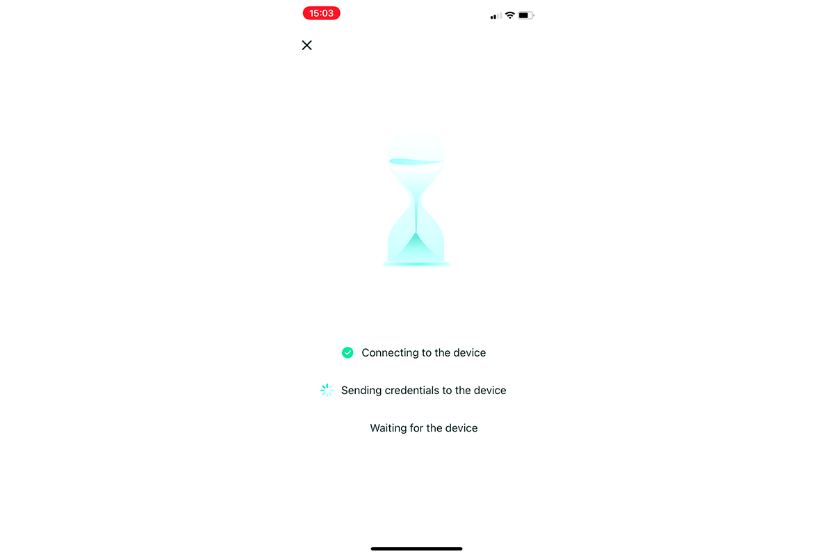
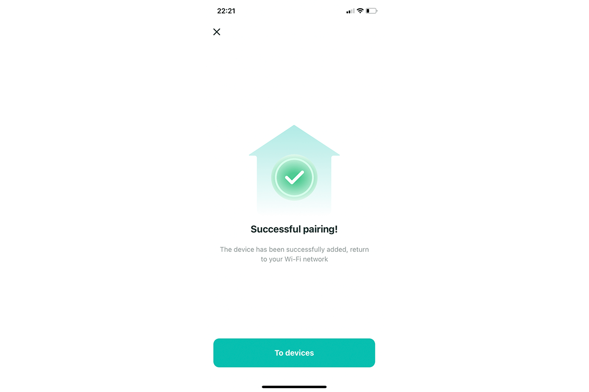
- Wait for the pairing to complete.
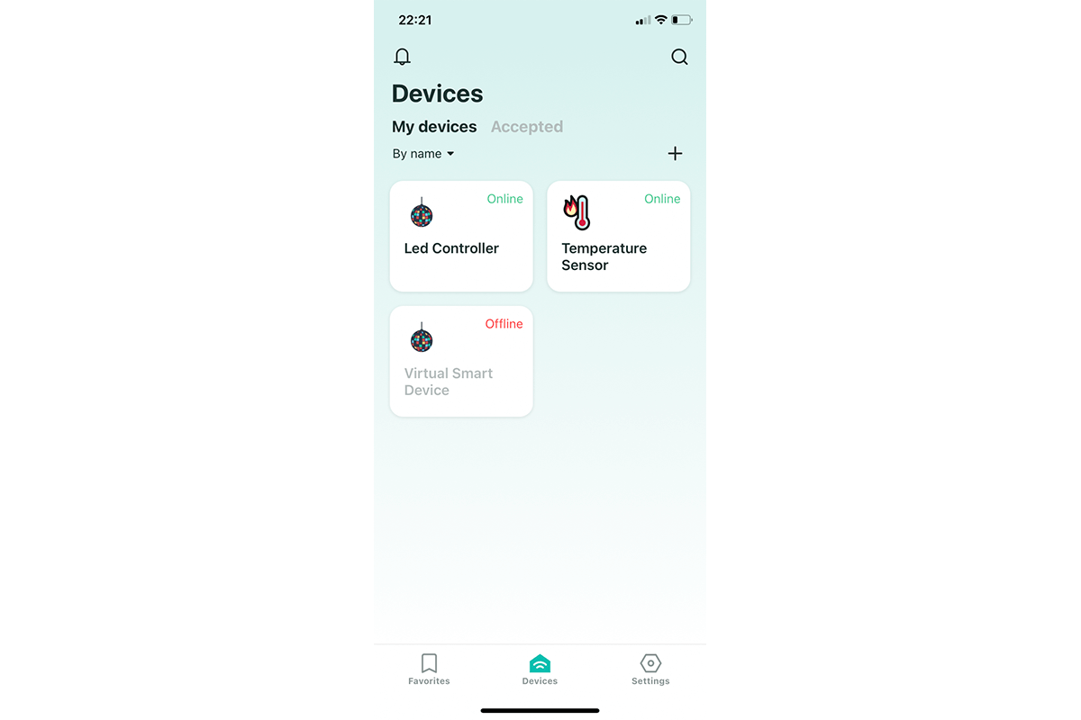
- Your controller is now displayed on the Devices screen. You can control its functions using a mobile application and additional methods: voice commands, phone calls, a Telegram bot.


Method two: with flashing the device
- Clear the microcontroller memory – on Mac OS, use the following command:
./2smart.sh erase_flash -d /dev/tty.SLAB_USBtoUART
- Upload the firmware to the device – in Mac OS, use the following command:
./2smart.sh write -d /dev/tty.SLAB_USBtoUART
- Pair the device to the mobile application in the same way as the instructions for the first method.
In both cases, the same controller is first used as a test device, and then as a finished product. We recommend having at least two controllers so that one of them always remains connected to the platform as a prototype.
The test device will allow you to work on new modes for the LED strip. Its firmware can be updated both via cable and over the air via the controller’s web interface (the firmware is installed on the Settings page). You can connect to the controller’s web interface using its local IP address, which is provided in the 2Smart Cloud mobile application.
After adding new modes or modifying the firmware for other purposes, you can upload the updated firmware file on the product page. All existing controllers will receive an update over the air. Read more about the mechanics of updating the firmware and delivering updates in this article.
Results
We showed how to assemble a smart device using the available components. Ready-made firmware for the LED strip controller is available on GitHub, so you can use it unchanged on your devices. Also, you can take our code as a basis and modify the controller modes by adding new effects (more about how to add your effect for an LED strip controller).
Additionally, we prepared a second article regarding the same device. It details the process of developing ESPHome-based firmware. With it, you can create a compatible firmware for the controller using a simple tool that does not require the ability to program and use assembly programs on a computer.
The development of this idea is an IoT smart lighting solution where the controller described above controls the LED matrix, which is the basis for a smart lamp with multiple effects.
Don't forget to share this post!
Read Next


Let’s dive into your case
Share with us your business idea and expectations about the software or additional services.
