
Table of contents:
The primary tool for creating firmware for an ESP32-based IoT device in 2Smart Cloud is the Software Development Kit (SDK) developed by the platform team. Now we’ll talk about the benefits of SDK firmware, which developers automatically receive, as well as instructions on creating firmware for the simplest IoT device.
2Smart Cloud’s SDK functionality: tool benefits
The basic principle of firmware SDK is that the code for integrating the device with the platform is already written. Thus all the developer has to do is describe the logic of his/her product.
In addition to the full integration with the platform, the SDK firmware provides additional functionality:
The built-in web admin panel of the device

This tool allows to configure flexible settings and receive more telemetry data than in a mobile application. The developer can grant the user of the mobile application access only to the device’s primary functions. The advanced user will gain access to additional features after switching to the web interface.
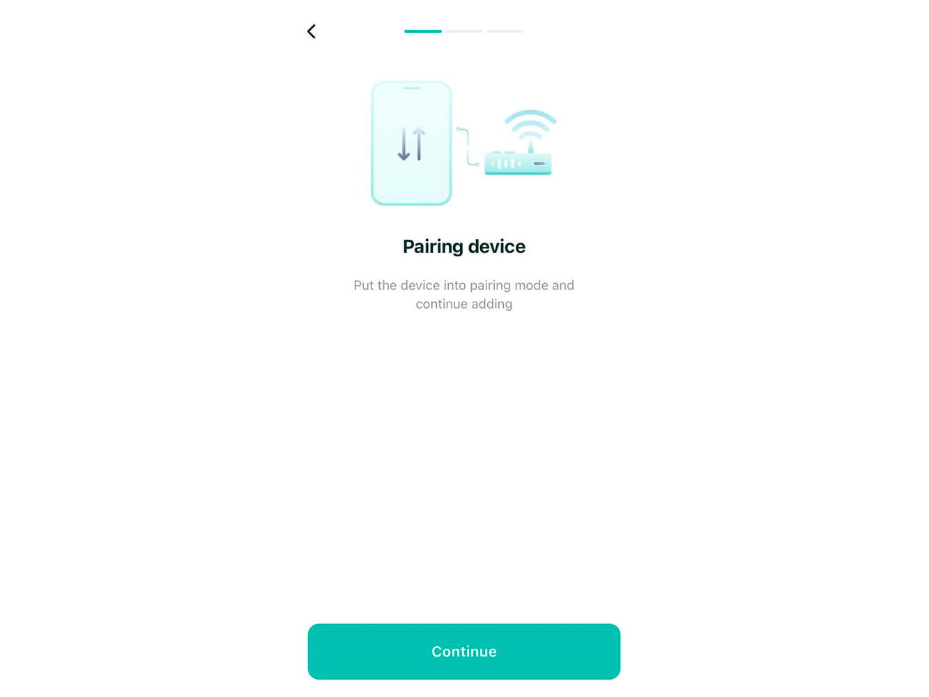
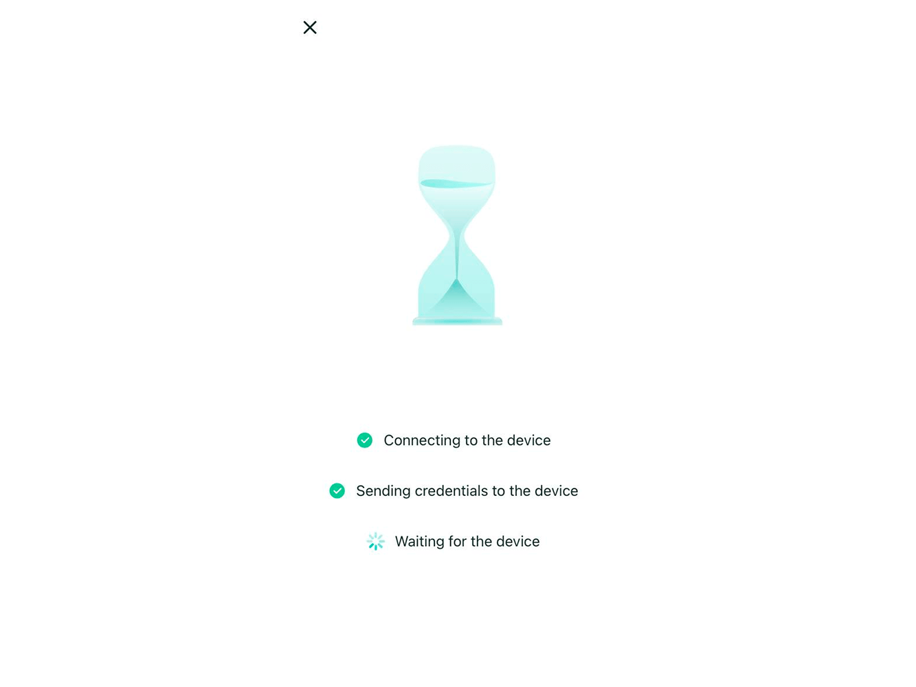
Quick device pairing
To connect the device with the mobile app, simply follow the standard procedure for all smart devices, which involves transferring Wi-Fi network data to the device.
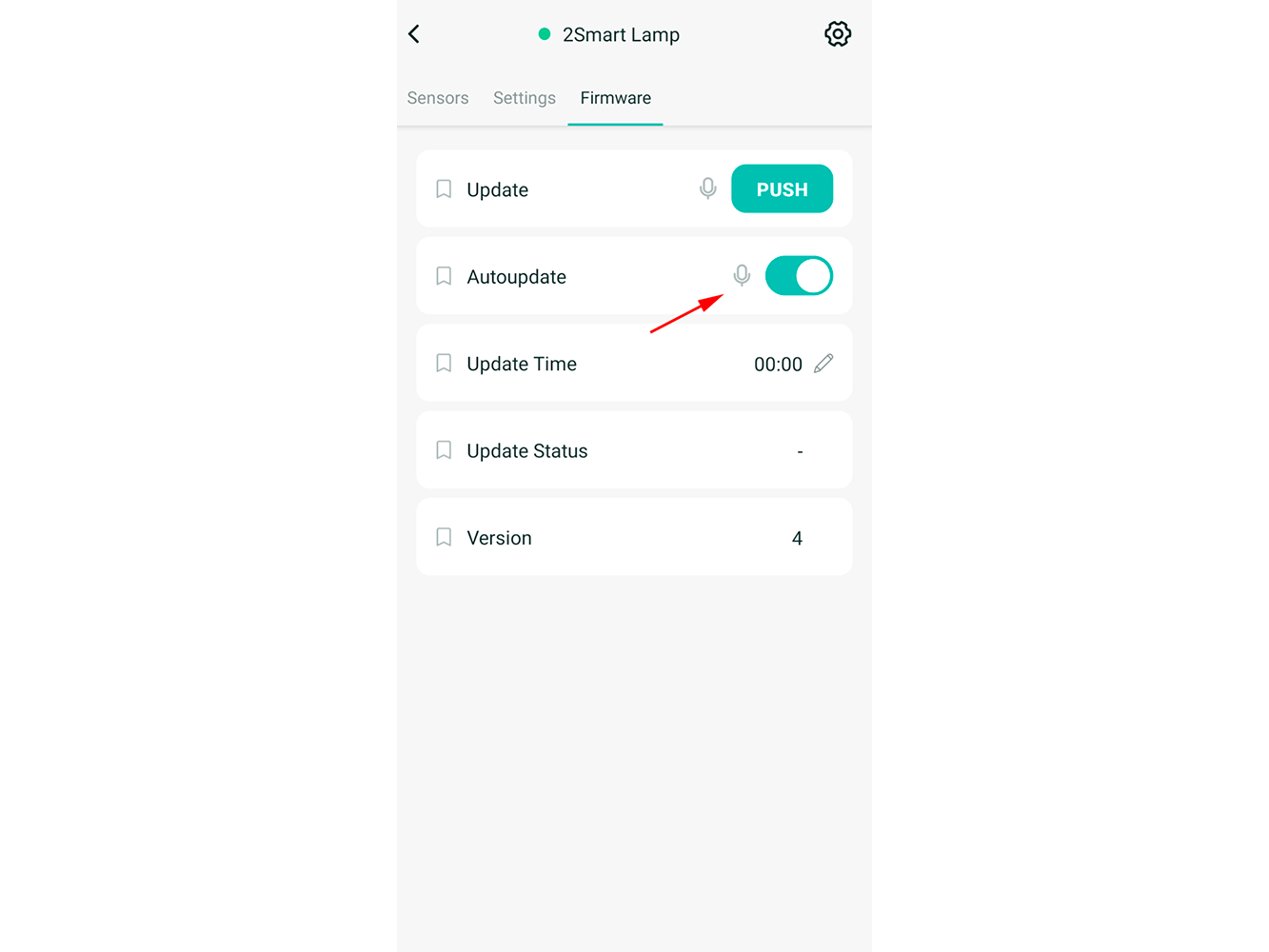
Automatic over the air firmware update
All that is required is for the developer to upload the latest firmware file to the system. The connected devices will automatically receive the update without further user intervention. It is sufficient to enable the mobile application’s auto-update firmware option.
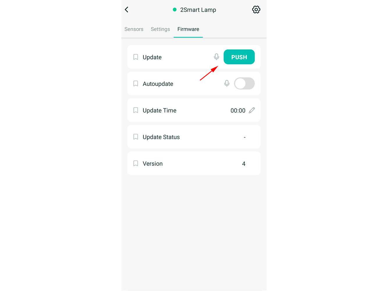
Manual over the air firmware update
Users can opt-out of getting firmware updates automatically, in which case updates will be delivered via request from the mobile application.
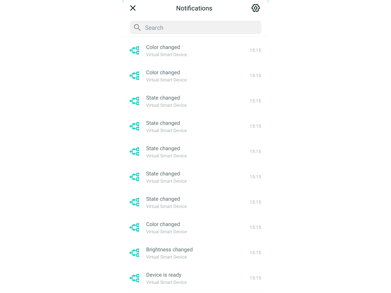
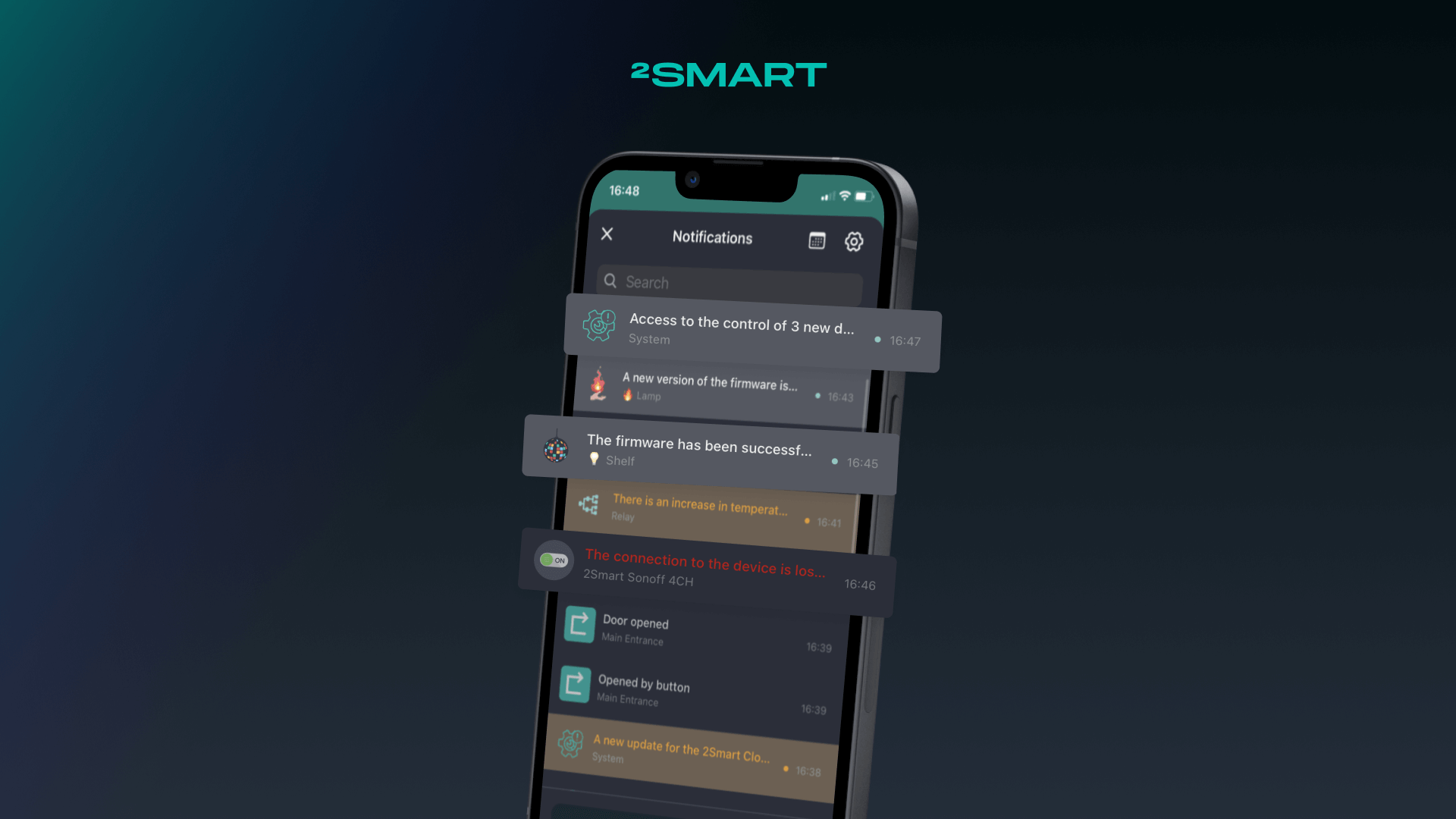
Device status notifications in the mobile app
The user can receive notifications about turning on/off the device, switching its functions, etc.
How to write firmware using SDK
Let’s look at how to write firmware for the most basic device – a blinker-beacon – using the SDK:
- Download our SDK from GitHub – https://github.com/2SmartCloud/2smart-cloud-cpp-sdk.
- Create a new project in the source code editor – in our example, we used Visual Studio Code. Specify the name of the project and select the appropriate board and framework.

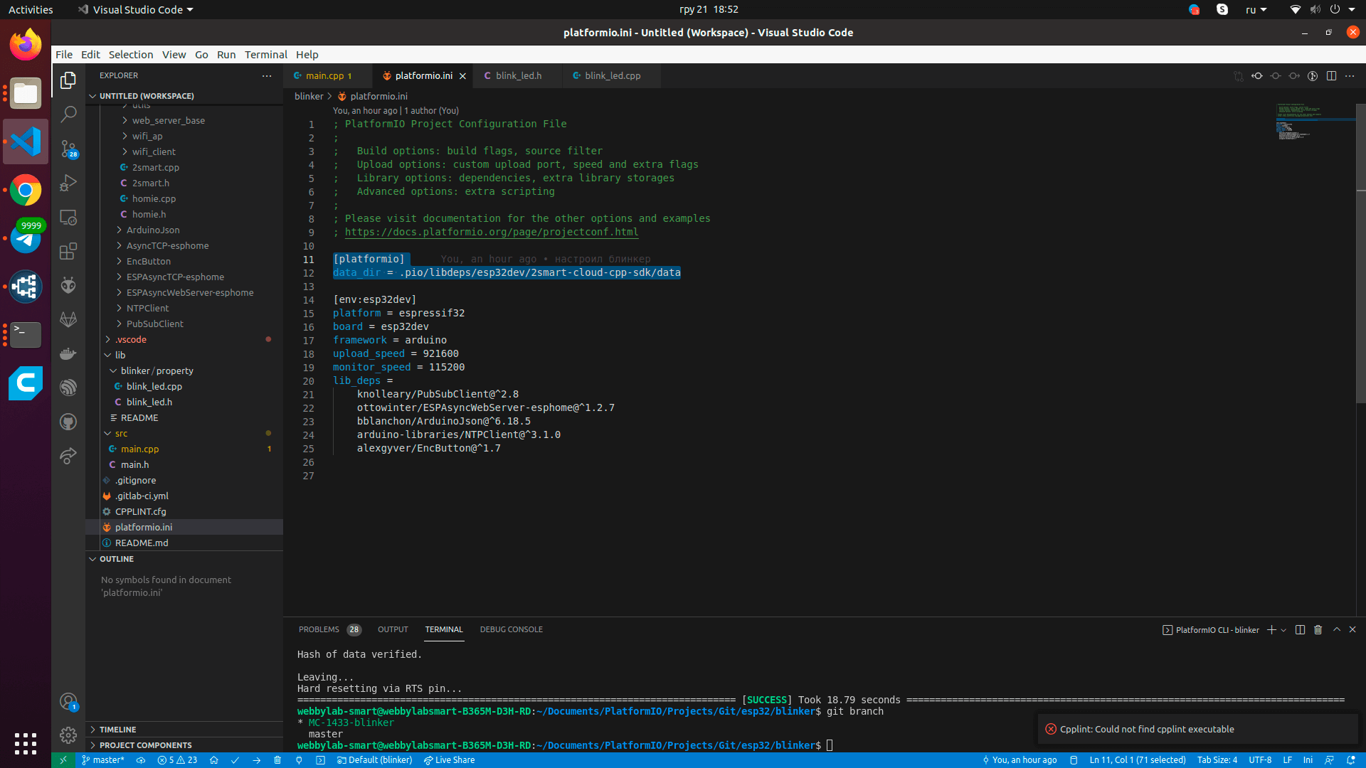
- Connect the necessary libraries in the platform.ini file of the downloaded SDK:
- PubSubClient – for working with MQTT,
- AsyncWebServer – for the web admin panel to work and accept credentials when pairing a device,
- ArduinoJSON – to work with JSON lines,
- NTPClient – to synchronize the current time and update the firmware at the specified time.
- Add the following code to the platform.ini file to connect the web interface functionality.
- Create a folder to describe the logic of your device (in our example, a blinker) in the lib/ or src/ directory.
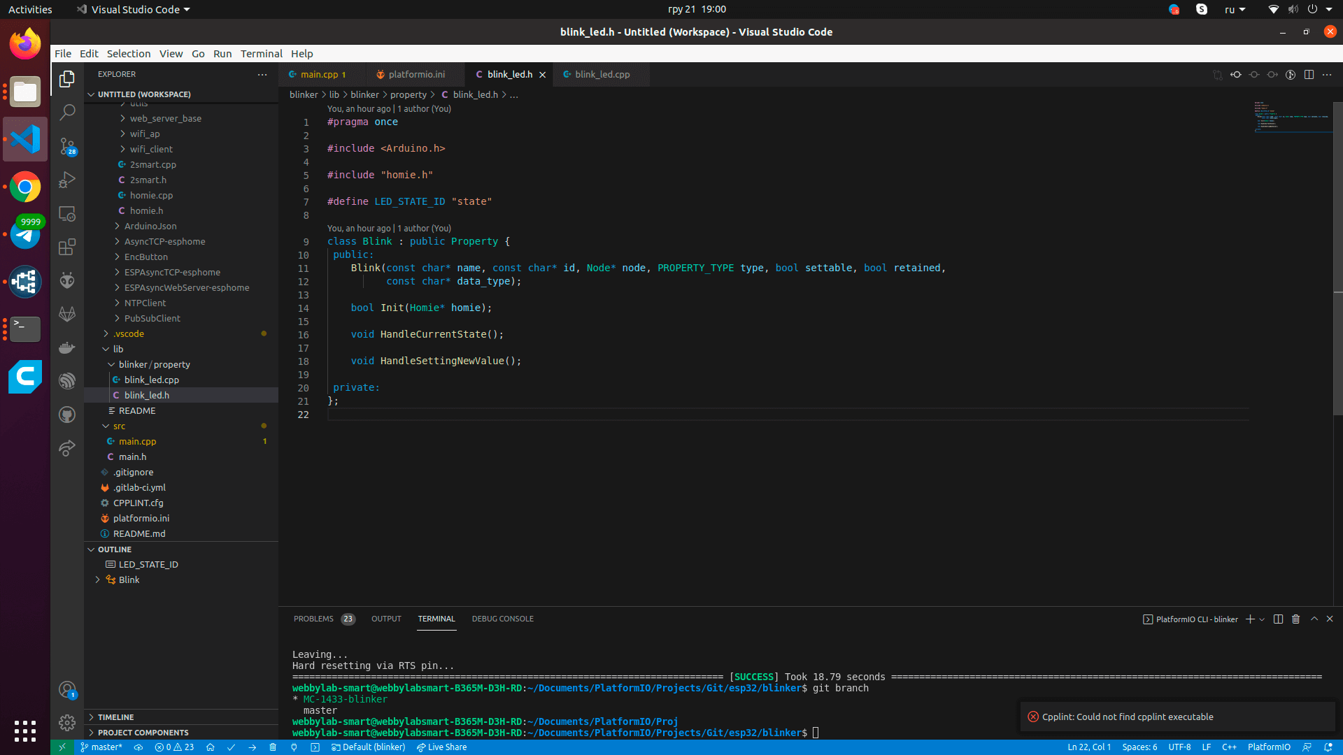
- Create standard files with the extension .cpp and .h – in our example is blink_led.cpp and blink_led.h.
- In the .h file, create a child class Property. Include your fields and methods as needed.
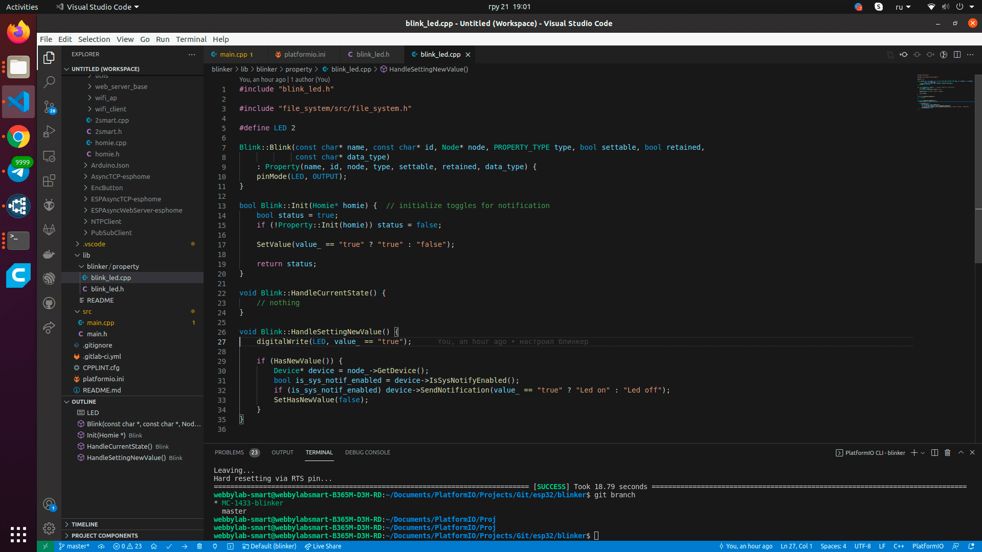
- In the .cpp file, describe the implementation of the methods.
Code explanation:- lines 7-11 – creating a class object;
- lines 13-20 – initialization;
- line 17 – setting the value of our property so that it is not undefined;
- lines 22-24 – the method is usually used to track the sensor’s status. However, since our LED will only change its state on command from the phone, this method is not needed yet. Use this method to poll buttons or sensors of devices more complex than a blinker;
- lines 26-35 – the method is called whenever the sensor value is changed by the user using the application, and here it is necessary to describe the logic. In our example, on line 27, the LED is passed the value “on” or “off”. If this value has changed, a notification sent to the mobile application.
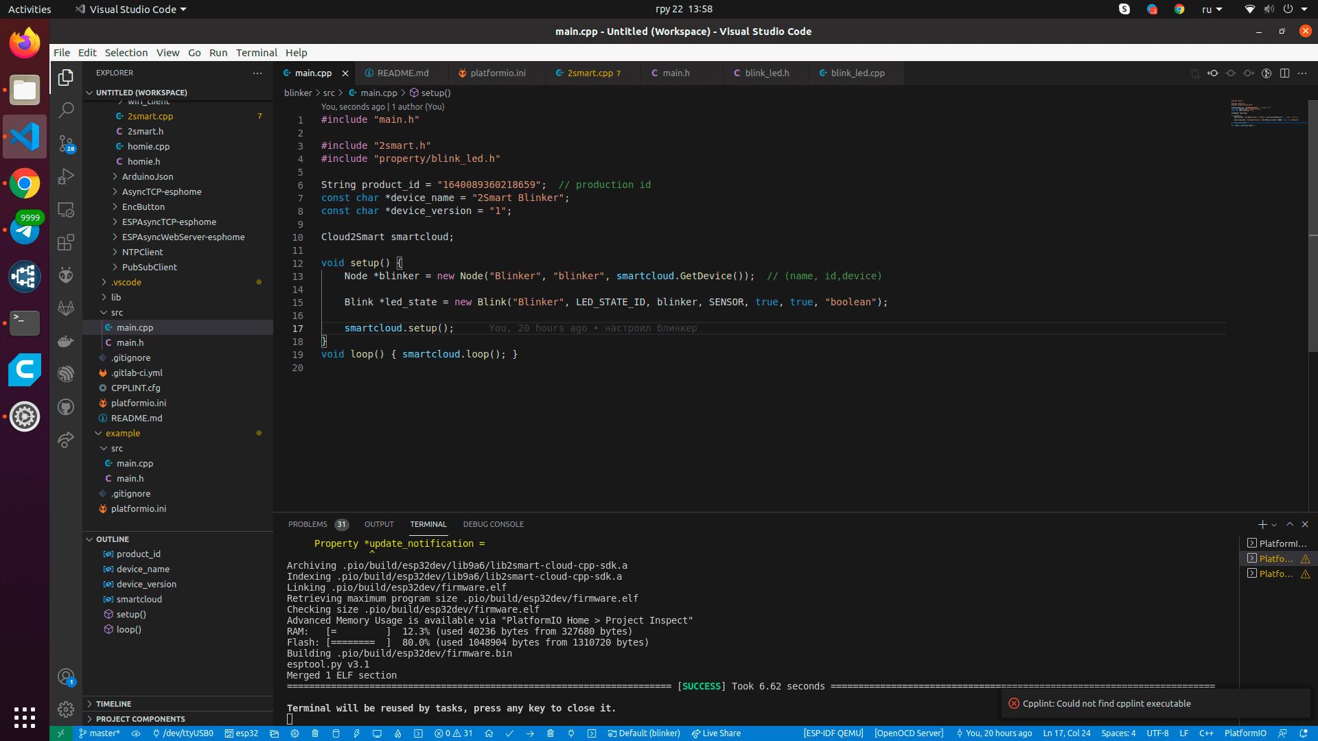
- Go to the main.cpp file and make the necessary changes.
Explanations:- line 3 – connecting our library;
- line 4 – connecting to a previously created property;
- line 6 – ID of our product (it is not known yet – we will make a new product on the platform a little later and return to editing this file);
- line 7 – the name of the device, as well as the name of the Wi-Fi access point that the device will launch at the pairing stage (enter any value);
- line 8 – firmware version number (for a new device, specify “1”);
- line 10 – class object;
- line 13 – creating a node;
- line 15 – creating our property for the LED;
- line 17 – launching library initialization;
- line 19 – adding cyclic state processing by the library.


Let’s collaborate
We’re empower your business with our technology expertise
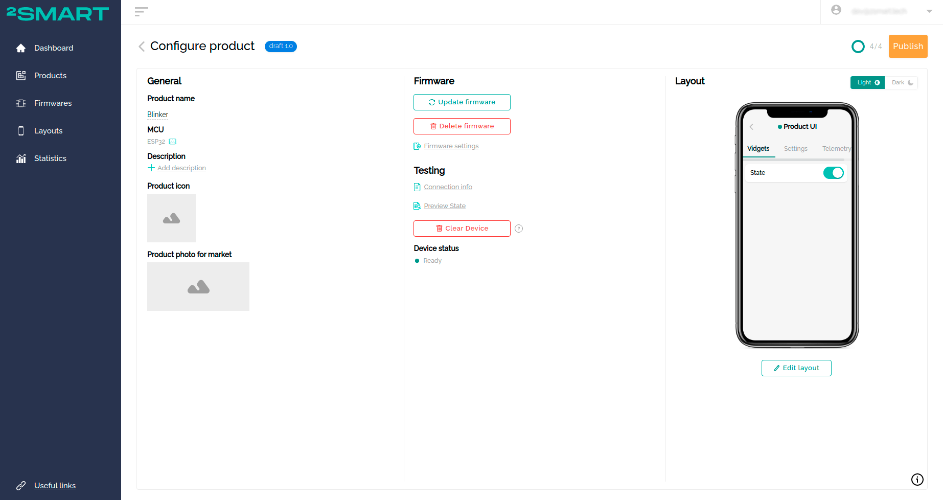
After writing the code, you can proceed to create a new product on the platform. Do not close the source code editor – you will still need to make changes to the firmware.
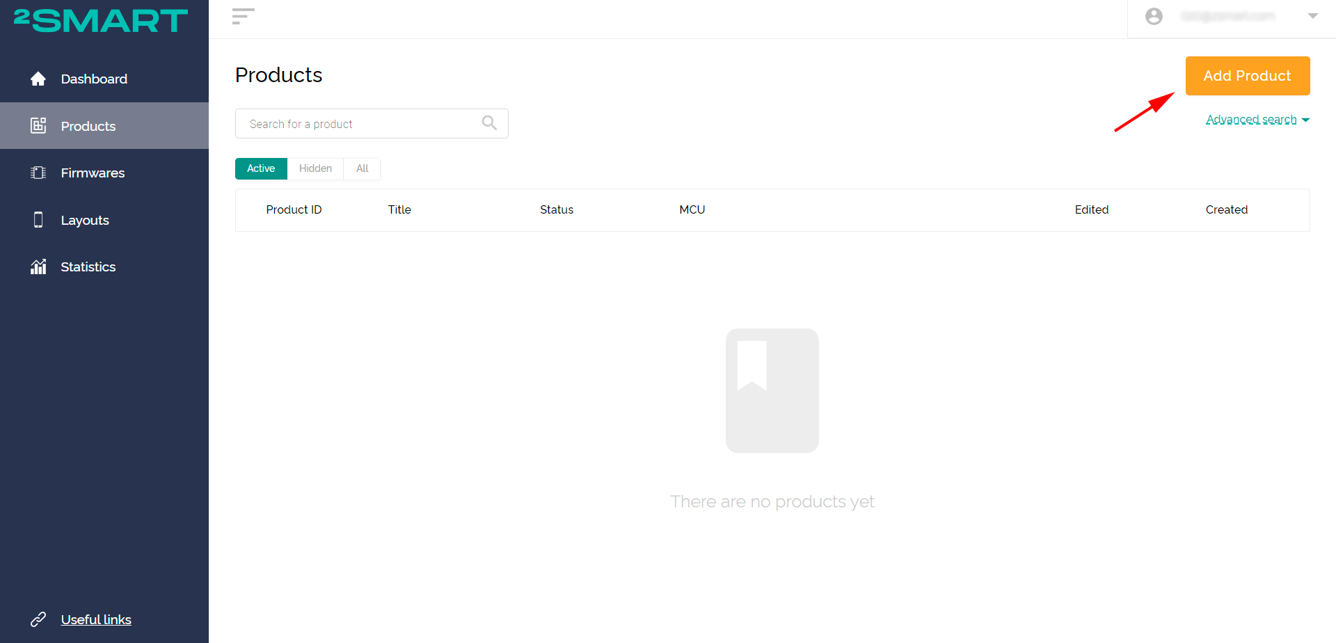
- Click “Add product” on the “Products” page of the vendor’s account.

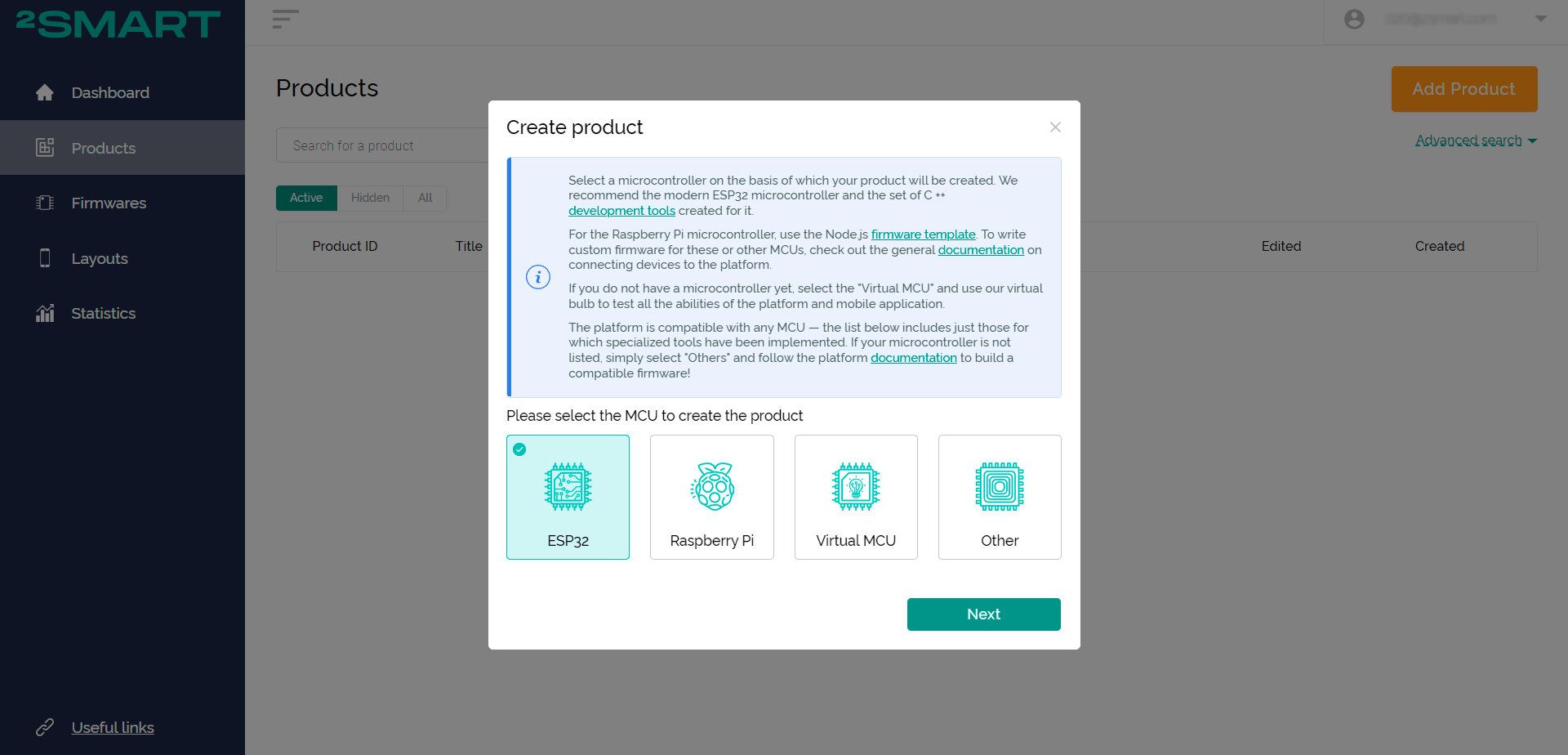
- Select the microcontroller – ESP32. Click “Next”.
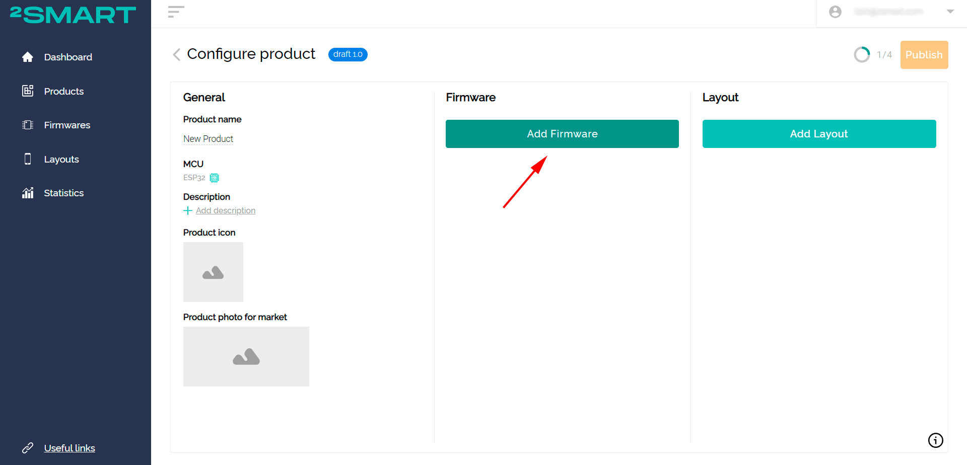
- Click “Add Firmware”.
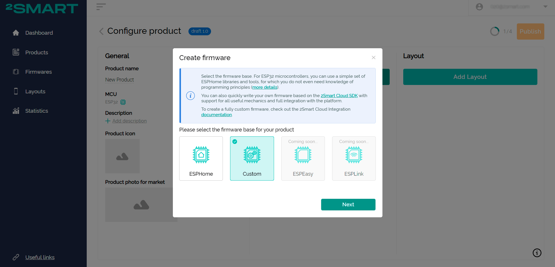
- Select the base for the firmware – Custom. Click “Next”.
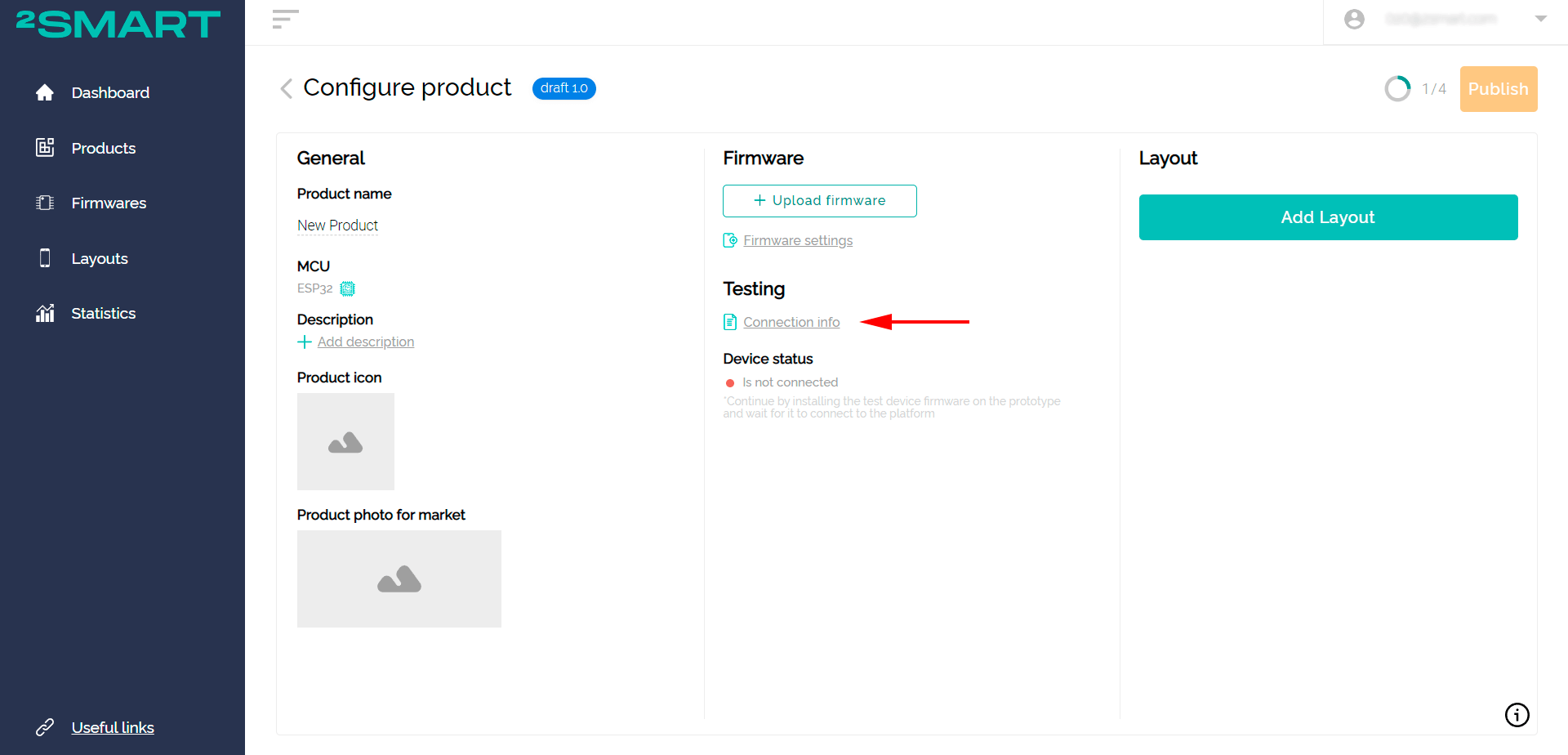
- Click on the “Connection Info” link.
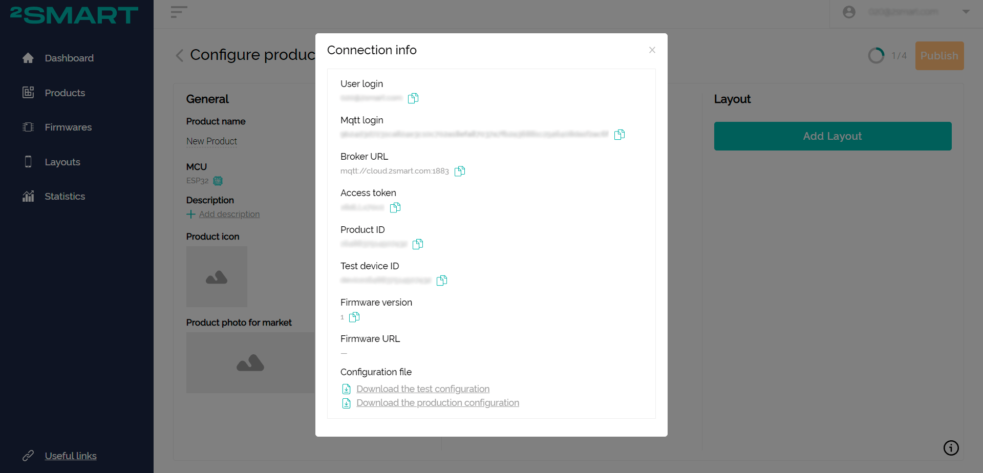
- Leave the connection data window open and return to the source code editor to continue working on the firmware.
- Copy the product ID into the product_id field of the main.cpp file of the firmware.
- Run the pio run -t uploadfs command to upload the file.
- Run the pio run -t upload command to upload the firmware to the device.
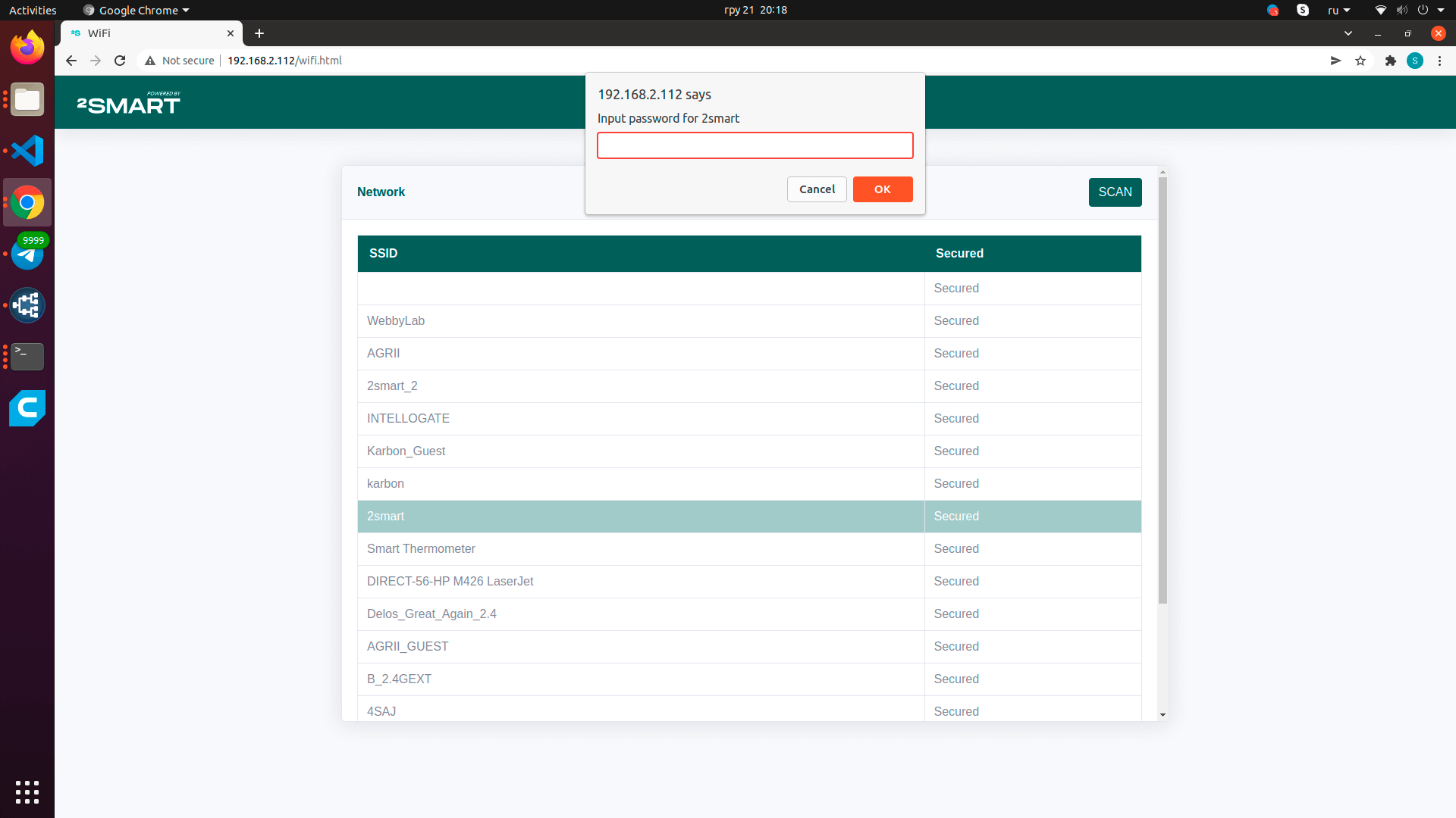
- Open the Wi-Fi settings of your computer or mobile device and connect to the hotspot that the blinker created – it has the same name as the device.
- Log in to the device’s web interface using the link#nbsp; http://192.168.4.1, use the username and password “admin”.
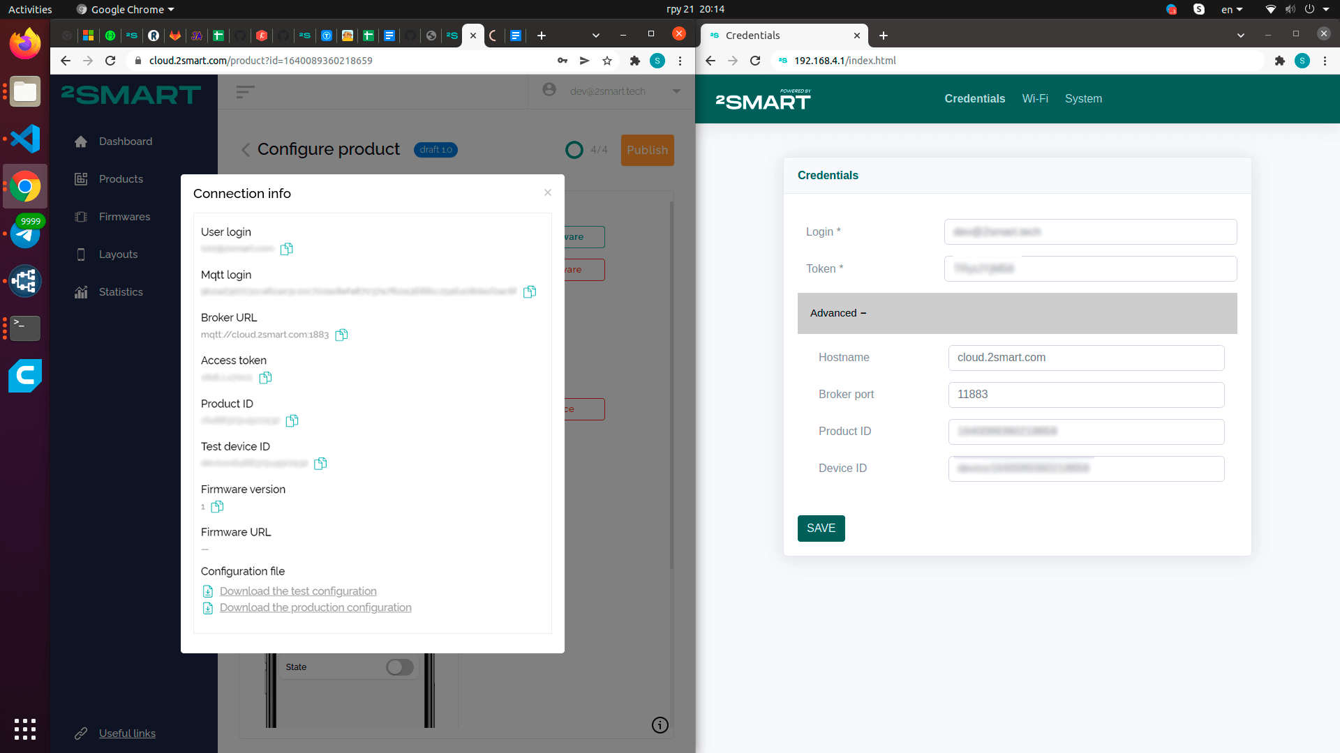
- On the Credentials tab of the web interface, fill in all the fields with the data from the “Connection Info” window opened in the vendor’s account – including those that are under the Advanced spoiler. Click Save.
- Wait for the device to reboot. After that, go to the web interface’s Wi-Fi tab, select your network from the list and enter your password. These credentials are necessary for the blinker to connect to the Internet.
Please note! ESP32 based devices only support 2.4GHz Wi-Fi networks! - Go back to your regular Wi-Fi network. The device’s status on the platform has changed to Ready, which means the blinker has connected to the platform.

- Configure the mobile application interface to control the device and check the prototype’s functionality. For more information about these stages of work on the product, see the article on connecting to the Wi-Fi relay platform.
- Download the firmware to the platform and click “Publish” – now you can connect the device to the mobile application according to the standard pairing procedure, available to all users.
Don't forget to share this post!
Read Next


")


Let’s dive into your case
Share with us your business idea and expectations about the software or additional services.
