
Table of contents:
Platform vendors using the ESP32 microcontroller in their projects have two firmware development tools available: ESPHome and the 2Smart Cloud Software Development Kit (SDK). We will talk about the pros and cons of these tools and demonstrate with a simple example how to work with each of them.
The main differences between ESPHome and SDK
Simplicity – is a key advantage of the ESPHome suite of libraries and tools. To develop firmware on this basis, you don’t even need to know the principles of programming. The main drawback is the limited functionality of the firmware.
It is developed by the 2Smart Cloud SDK team and supports all useful mechanisms and full device integration with the platform. The functionality of the firmware created on this basis is much wider than in the case of ESPHome. In addition, SDK development is a priority for the team, so all new platform functions will, first of all, appear in this database. This means that vendors who have chosen the firmware version on the SDK will be able to quickly use the innovations of 2Smart Cloud in their products.
Vendors can use the SDK-based code samples posted on the 2Smart Cloud GitHub as templates for the firmware of their devices, changing and modifying the code in any way.
The basic principle of creating firmware using the SDK is that the code has already been written to integrate the device with the platform, it is enough for a vendor to describe the logic of their product.
The comparative table below shows what functionality is available when using each of the options:
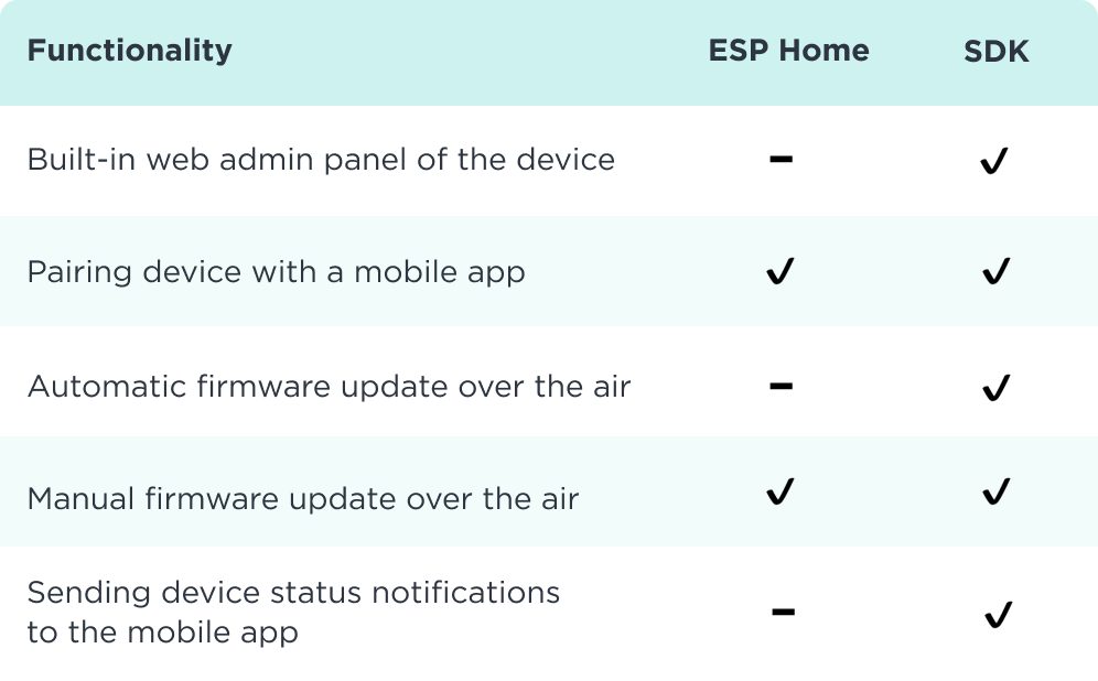
Which of the options for the firmware base for the ESP32 microcontroller to choose depends on the vendor’s needs and its resources. In many cases, the best option is a combination of the two – due to its simplicity, ESPHome is perfect for quick connection and initial testing of a device concept, and SDK-based firmware can be written for subsequent iterations of the prototype and the final version of the product.
Below it will be shown how to develop the firmware in each of the two ways. As an example, a simple device will be used – an LED (blinker) connected to the ESP32, which can be controlled from a mobile application and using additional methods available in 2Smart Cloud.
Development of a firmware for a blinker based on ESPHome
There are two ways to create a new product in 2Smart Cloud – with or without a step-by-step assistant. Read more about the differences between the two methods on the platform’s blog. In this example, we will use the option without a step-by-step wizard. The wizard-based alternative method is basically no different.
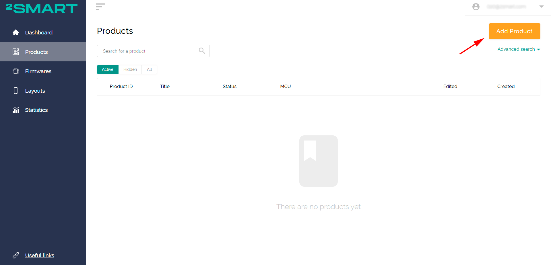
- On the Products page of the vendor’s account, click Add Product (a similar button on the main page launches the wizard option).

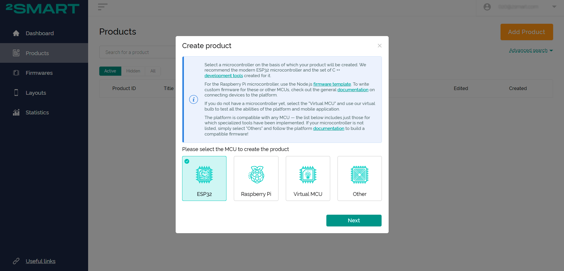
- Select microcontroller – ESP32. Click Next.
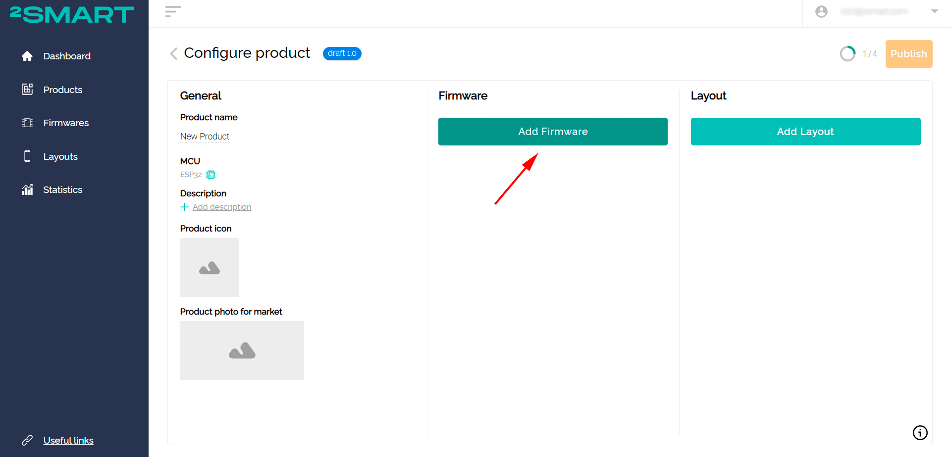
- Click “Add Firmware”.
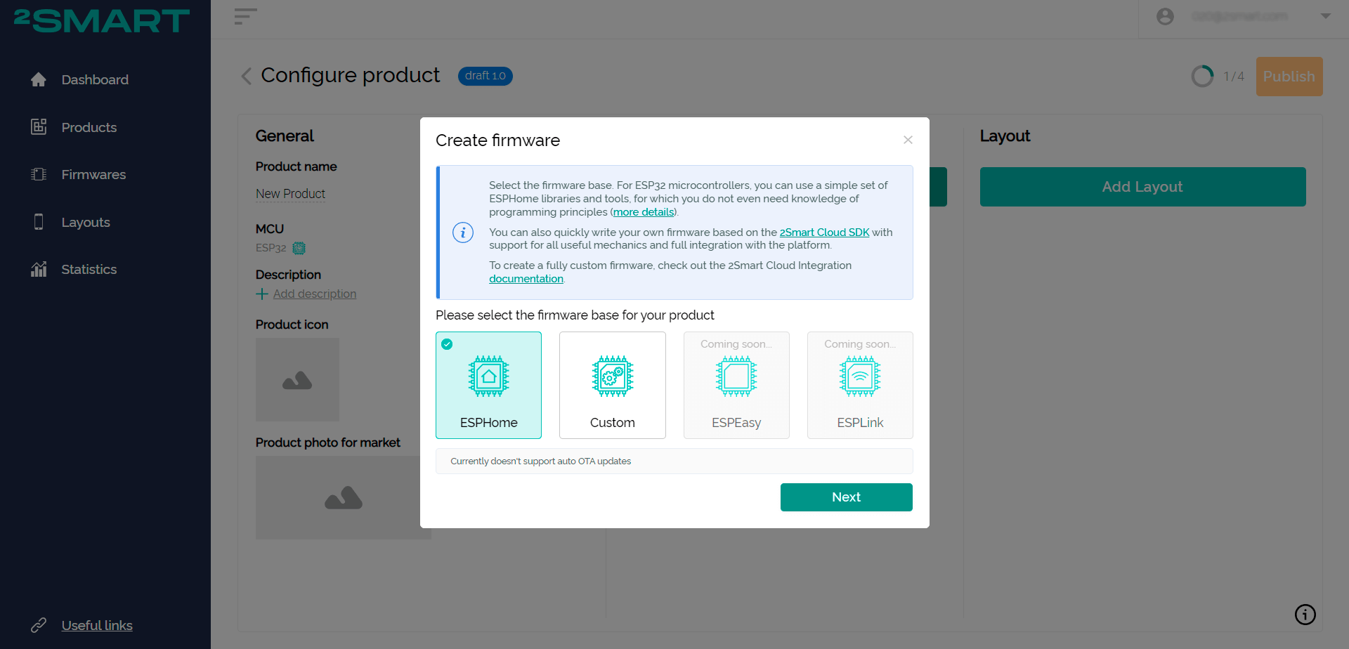
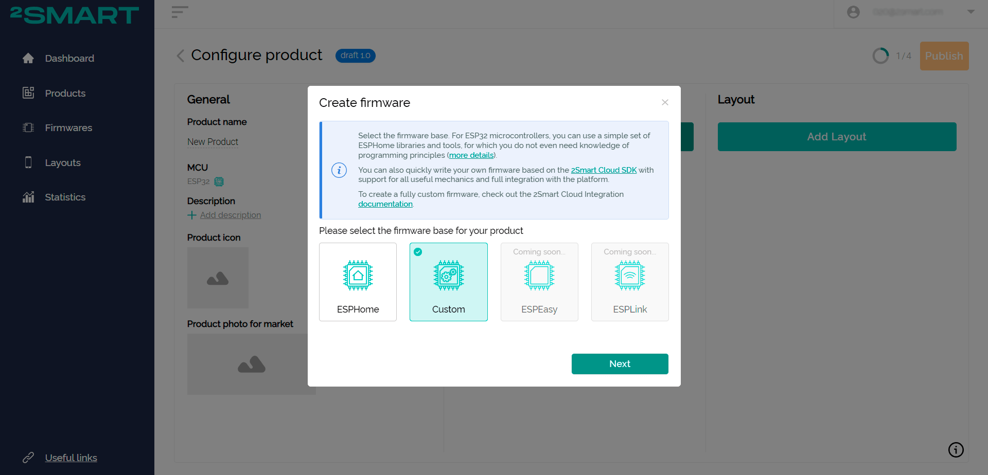
- Choose the ESPHome base for the firmware. Click Next.
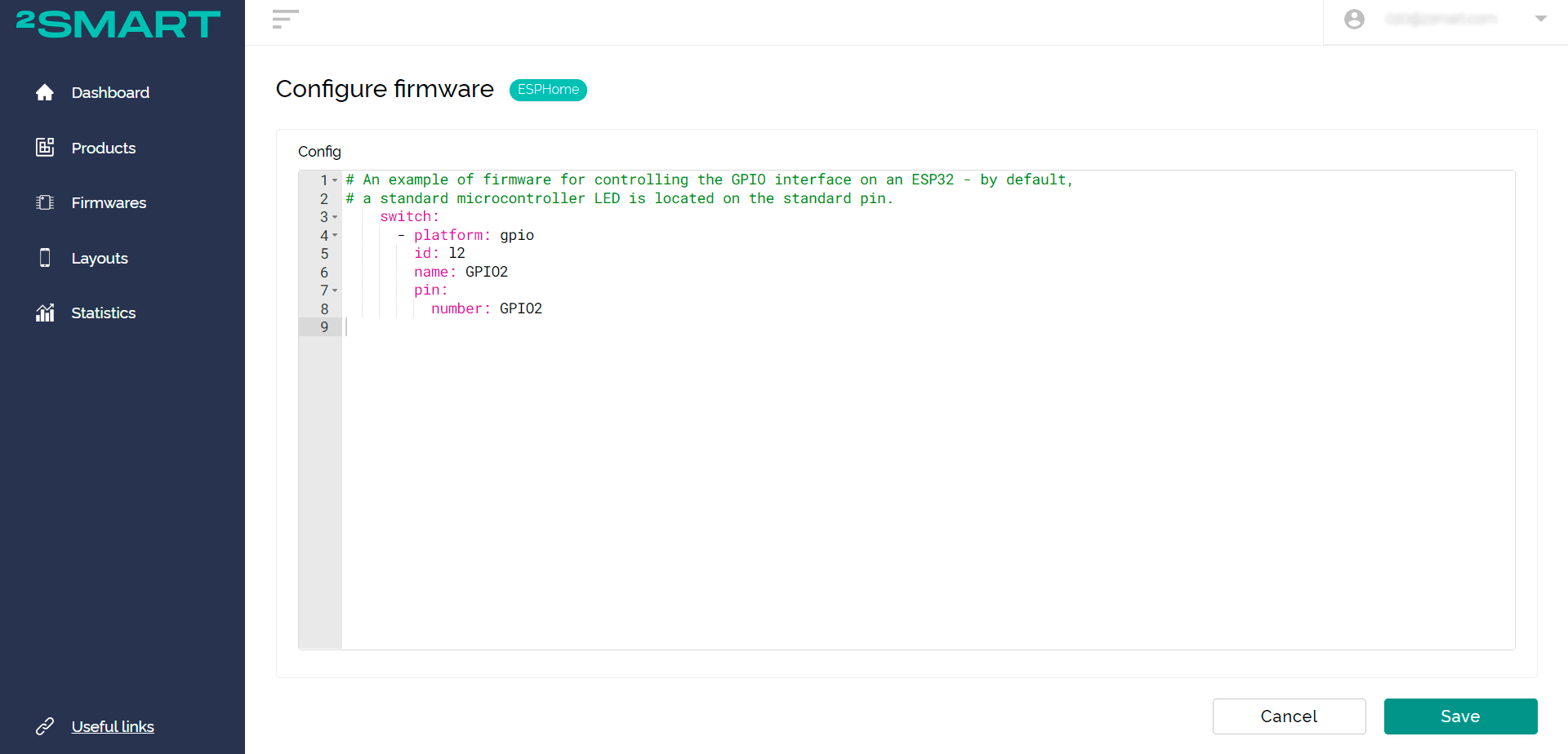
- Insert the firmware code of your device developed according to the documentation for ESPHome – the default blinker code is used as an example. Click Save.
- Click “Build Firmware” for the test device – it is used to connect to the platform and test the device before publishing.
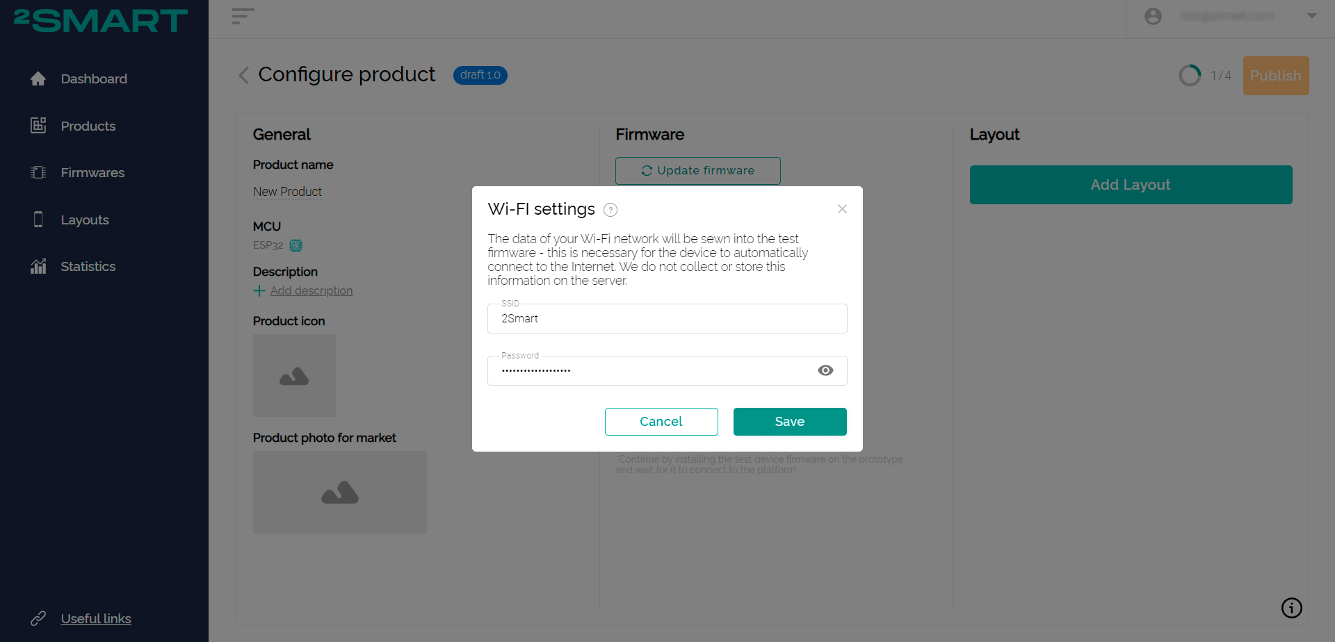
- Specify the details of your home or office Wi-Fi network – they will be entered into the firmware to quickly connect the device to the network.
Note! The ESP32 microcontroller only supports 2.4GHz networks! - Wait while the firmware file is assembled. In the case of ESPHome, the firmware is assembled on the server, you do not need to use special builders on your computer.
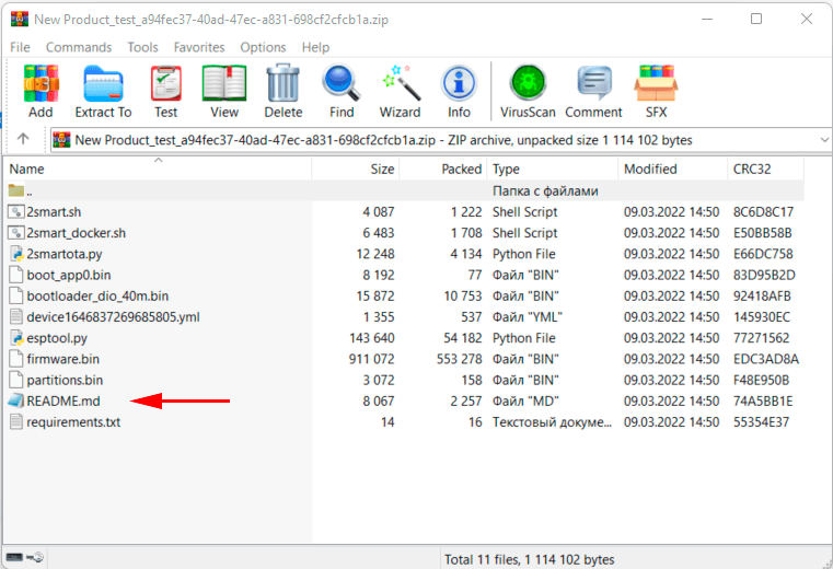
- Click Download.
- Use the downloaded file to upload firmware to your device – instructions are inside the archive in the readme.md file.

- Check the functionality of the product by connecting to the 2Smart Cloud platform.
Configure the mobile application interface for product management, install the application on your smartphone, and make sure the device is successfully controlled with it.
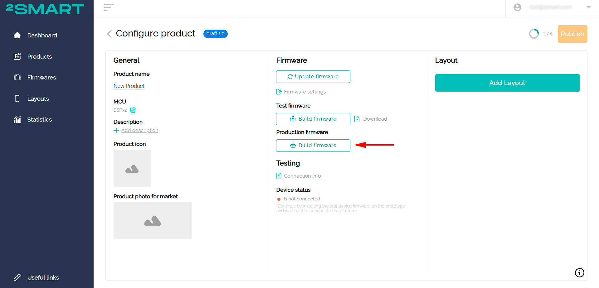
Read more about these stages of work on the product in the article on connecting to the Wi-Fi relay platform. - After making sure that the device works as you planned, build the final version of the firmware. To do this, click “Build Firmware” for the production version.
Unlike the Test firmware, the final version will not include your Wi-Fi data and other specific lines of code required for testing the product. - After assembling the final firmware, download the archive and install it on all your devices by analogy with installing the test version of the code.
- Publish your product to the platform. Do not forget to fill in the device information with the name, description and upload a logo with a photo of the product for the 2Smart Cloud market.


As a result, we received a workable IoT device that can be linked to the 2Smart Cloud mobile application and controlled from a smartphone. However, due to the limitations of ESPHome, the vendor and users will meet the following difficulties:
- no automatic firmware update – you need to force the user to start the process manually,
- sending notifications about the state of the device to the mobile application is not supported – for devices more complex than the blinker, this may be important,
- there is no built-in web admin panel – it can also be useful and in demand if you need the functionality of setting up a device in a local network without a mobile application.
Let’s collaborate
We’re empower your business with our technology expertise
Firmware development using SDK
The 2Smart Cloud Developer Kit solves these problems, which is why most vendors recommend using it when building the firmware of the finished product, even if the prototype has been tested with ESPHome-based firmware.
This is how the development of the firmware for the same device – blinker – looks like on SDK base:
- Download our SDK from GitHub – https://github.com/2SmartCloud/2smart-cloud-cpp-sdk
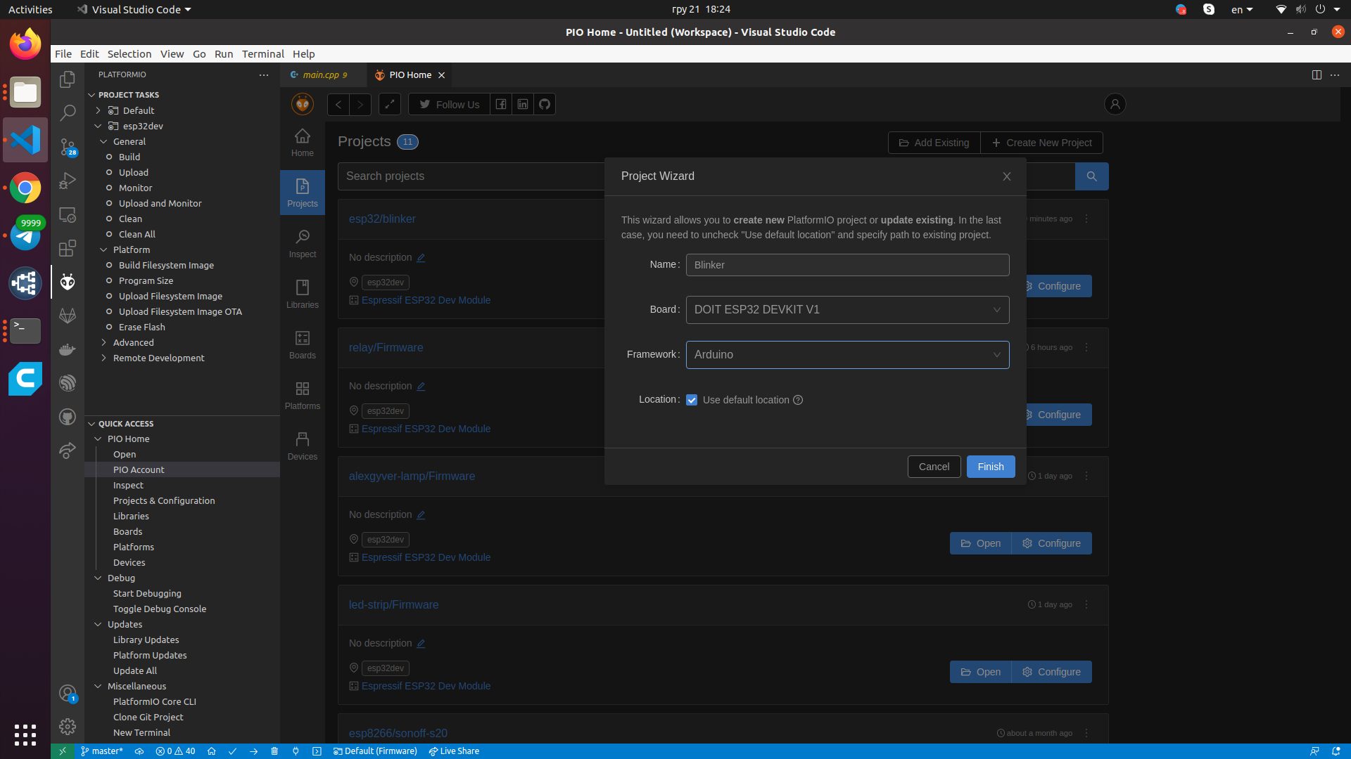
- Create a new project in the Source Editor – our example uses Visual Studio Code. Specify the name of the project, and choose the appropriate board and framework.

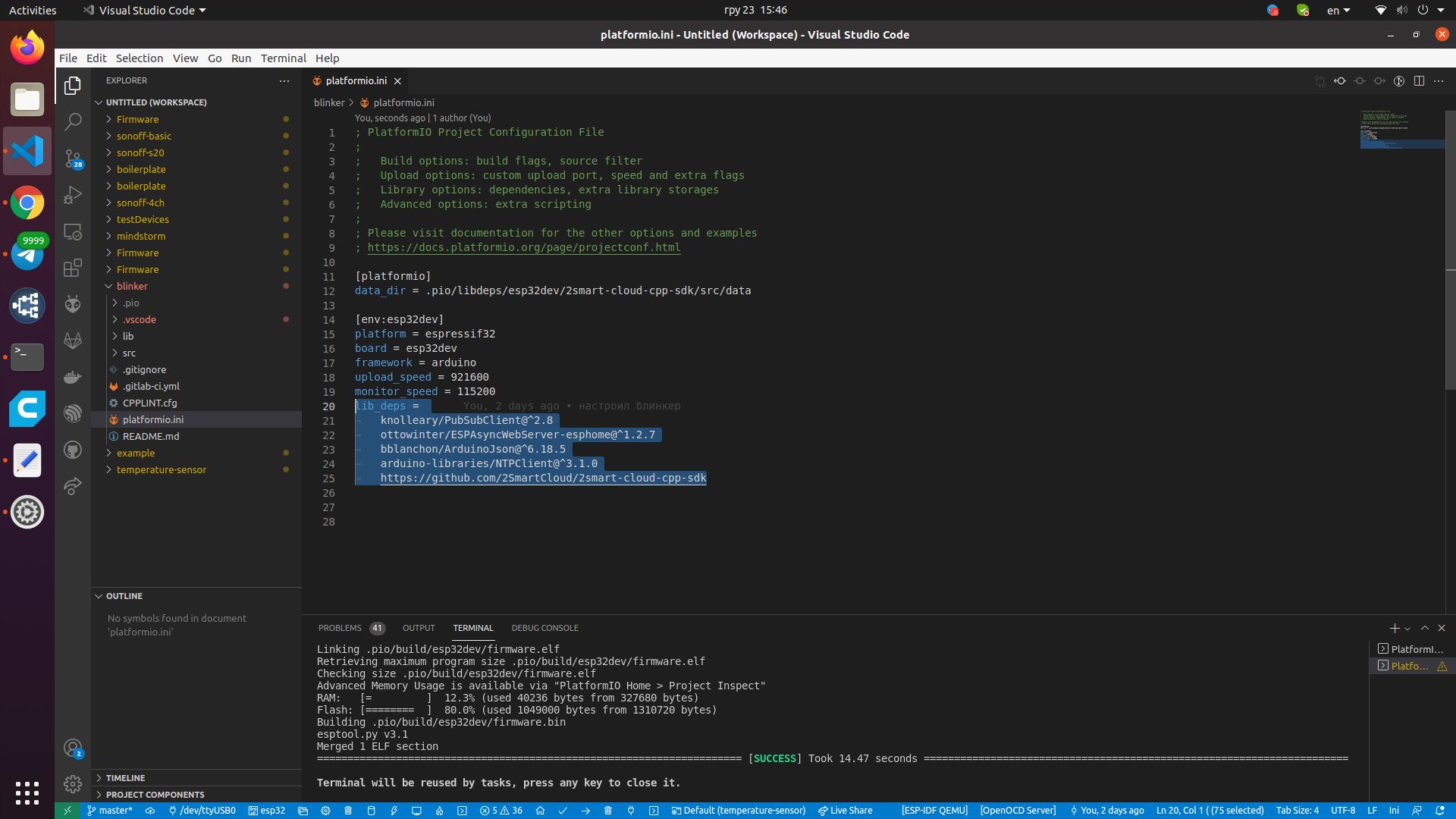
- Connect the required libraries in the platformio.ini file of the downloaded SDK:
- PubSubClient – for working with MQTT,
- AsyncWebServer – for running the web admin and accepting credentials when pairing a device,
- ArduinoJSON – for working with JSON strings,
- NTPClient – to synchronize the current time and update the firmware at a specified time of day.
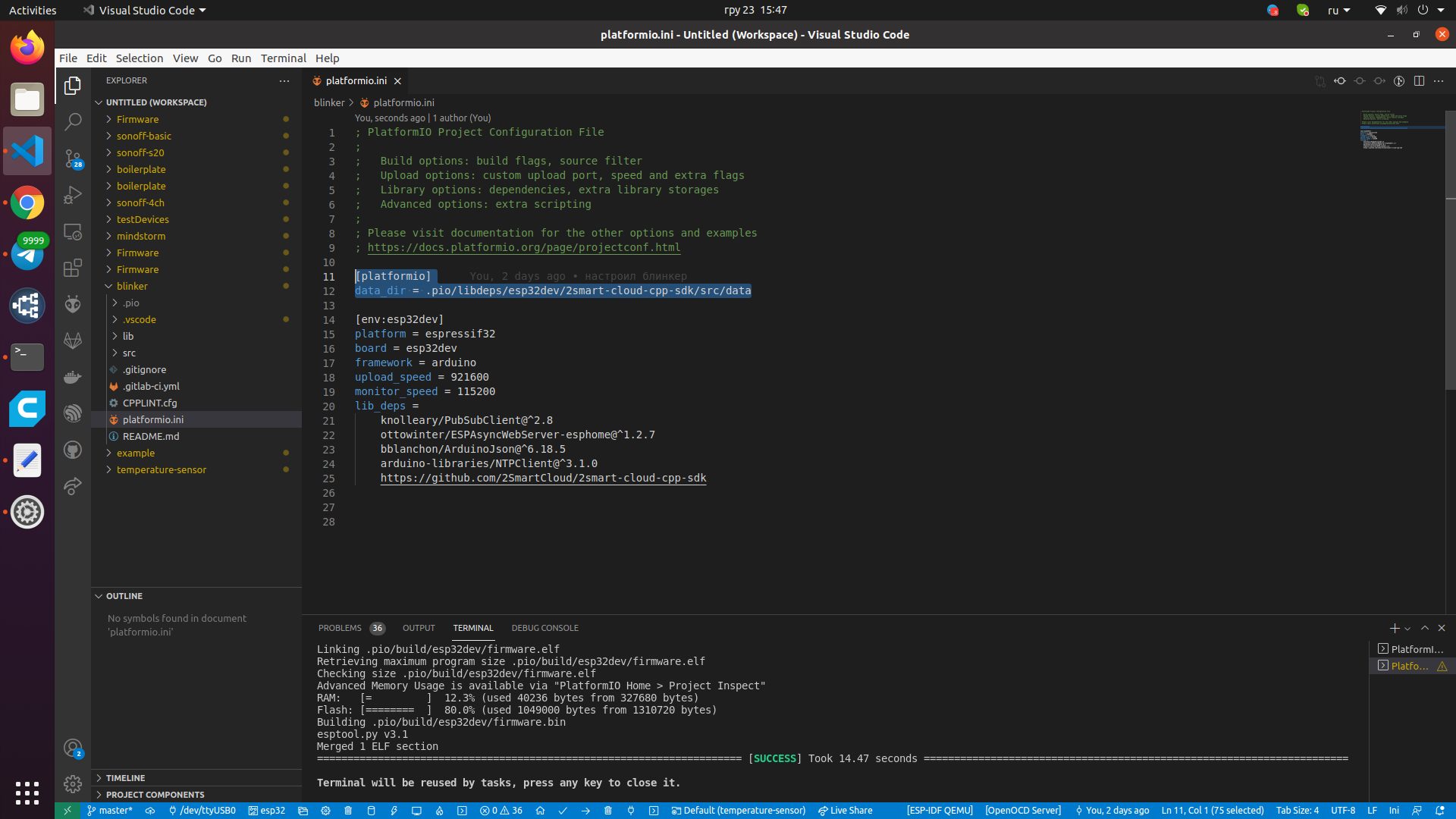
- Add the following code to platformio.ini to enable the web interface functionality.
- Create a folder to describe the logic of your device (in our example, blinker) in the lib / or src / directory.
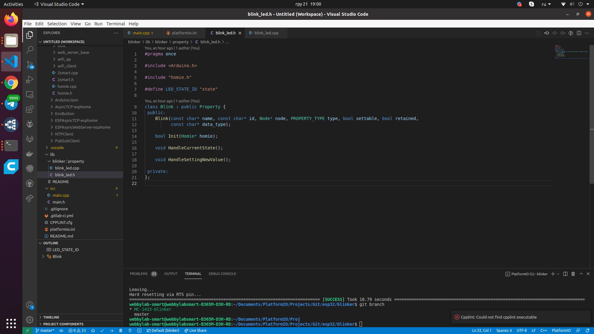
- Create standard files with .cpp and .h extensions – in our example, these are blink_led.cpp and blink_led.h.
- In the .h file, create a child Property class. Include your own fields and methods as needed.
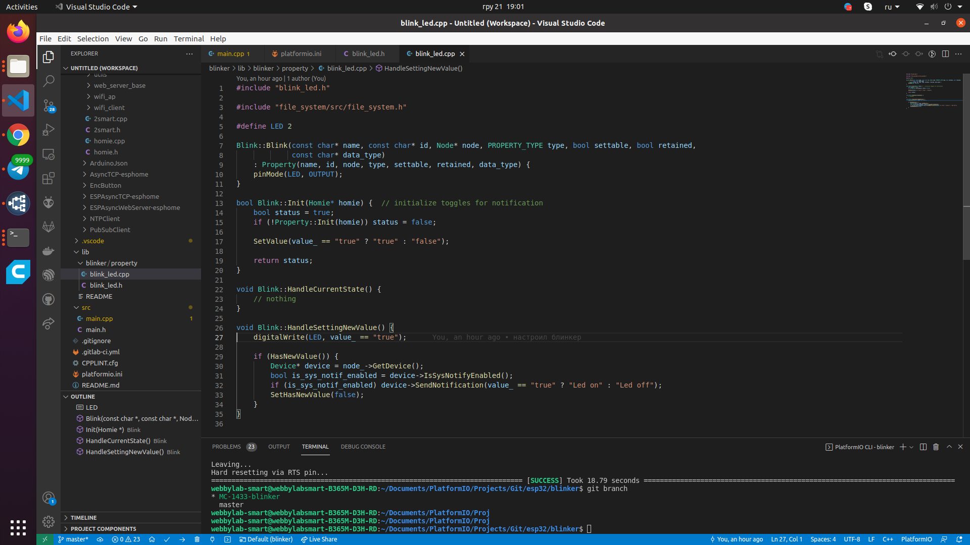
- In the .cpp file, describe the implementation of the methods.
Explanation of the code:- lines 7-11 – the class object is created;
- lines 13-20 – initialization;
- line 17 – the value of our property is set so that it is not undefined;
- lines 22-24 – the method is usually used to monitor the state of the sensor, however, since our LED will change its state only on a command from the phone, until this method is needed. Use this method to poll buttons or sensors that are more complex than a blinker device;
- lines 26-35 – the method is called whenever the sensor value is changed by the user using the application, and here you need to describe the logic. In our example, on line 27, the value “on” or “off” is passed to the LED. If this value has changed, a notification is sent to the mobile app.
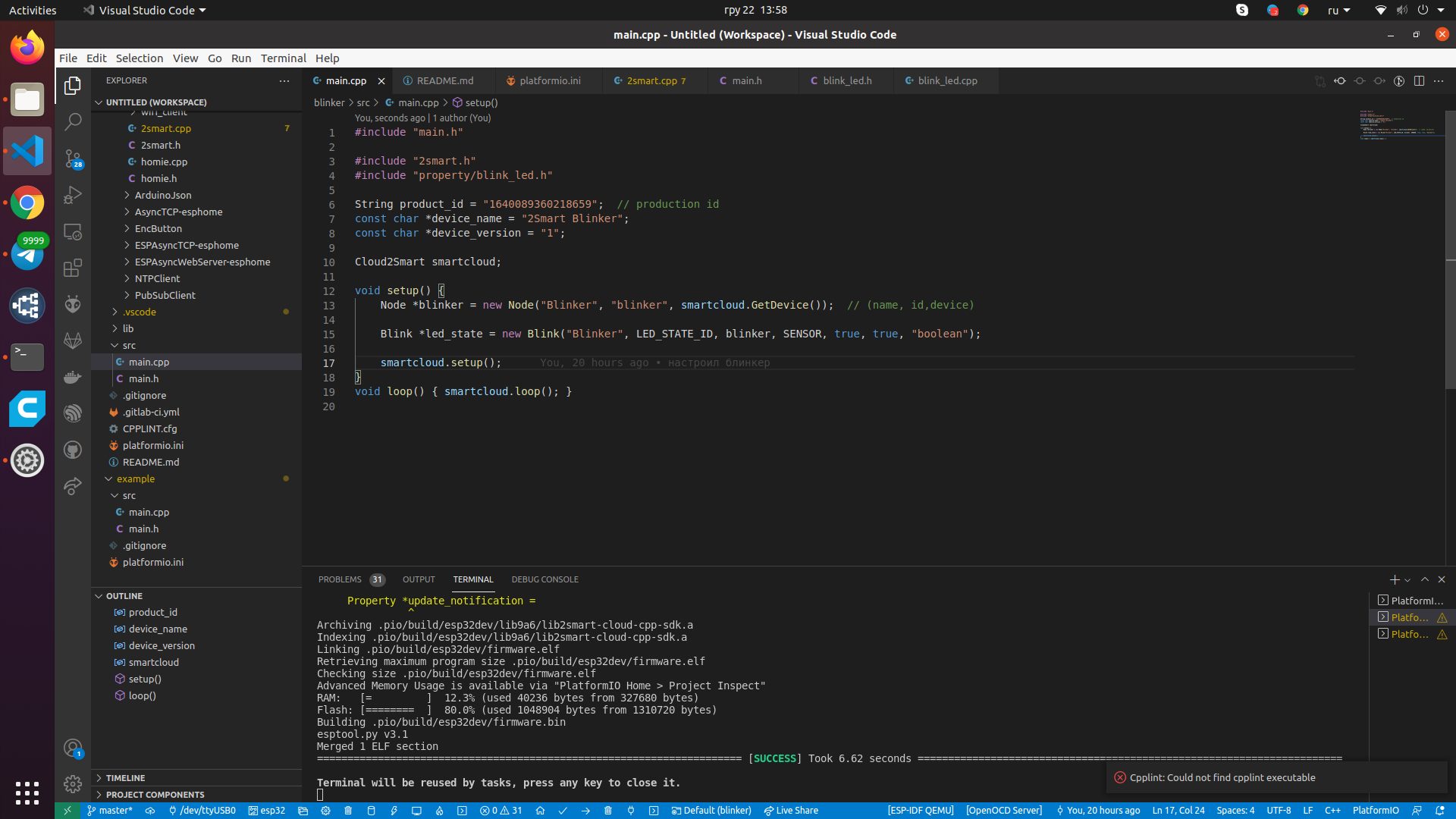
- Go to the main.cpp file and make the necessary changes.
Explanations:- line 3 – connecting our library;
- line 4 – connection of the previously created property;
- line 6 – ID of our product (not known yet – we will create a new product on the platform a little later and return to editing this file);
- line 7 – the name of the device, as well as the name of the Wi-Fi access point that the device will launch during the pairing stage (enter any value);
- line 8 – firmware version number (for a new device, specify “1”);
- line 10 – class object;
- line 13 – creating a node;
- line 15 – creating our property for the LED;
- line 17 – starting the initialization of the library;
- line 19 – adding cyclic processing of states by the library.
In fact, having written the code, you can move on to creating a new product on the platform. Don’t close the source editor – the firmware still needs some work.
- On the “Products” page of the vendor’s dashboard, click “Add product”.
- Select microcontroller – ESP32. Click Next.
- Click “Add Firmware”.
- Choose a Custom base for the firmware. Click Next.
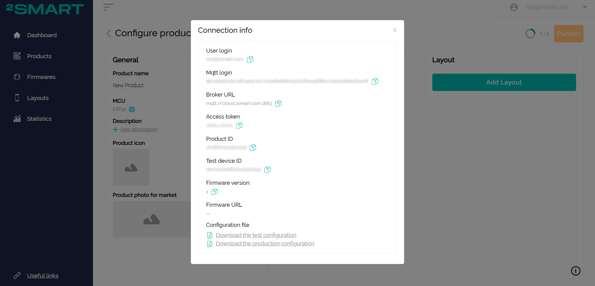
- Click on the “Connection info” link.
- Leave the connection data window open and go back to the source editor to continue working on the firmware.
- Copy the product ID into the product_id field of the main.cpp file of the firmware.
- Run pio run -t uploadfs to upload the filesystem to the device.
- Run the pio run -t upload command to upload the firmware to the device.
- Open the Wi-Fi settings of your computer or mobile device and connect to the access point created by the blinker – it has the same name as the device itself.
- Log in to the device web interface at http://192.168.4.1, use the “admin” login and password.
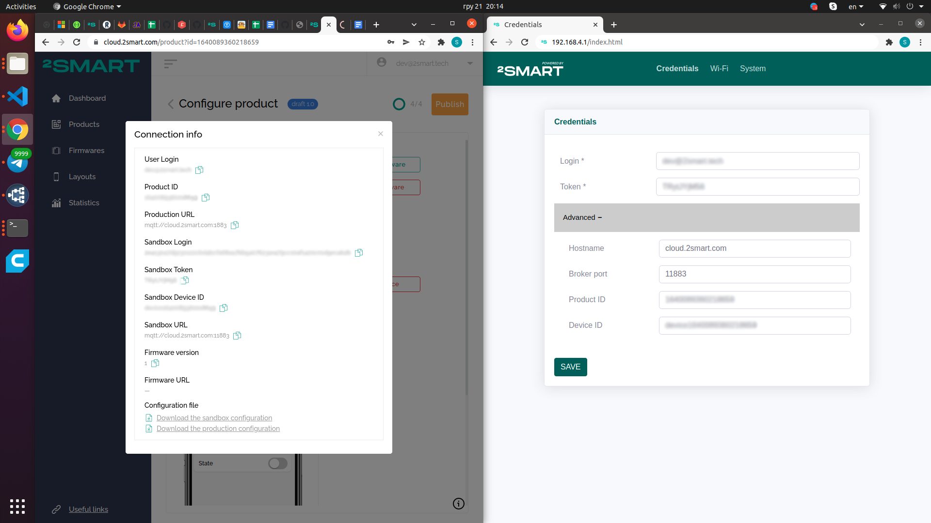
- On the “Credentials” tab of the web interface, fill in all the fields with the data from the “Connection info” window opened in the vendor’s account. Including under the Advanced spoiler. Click Save.
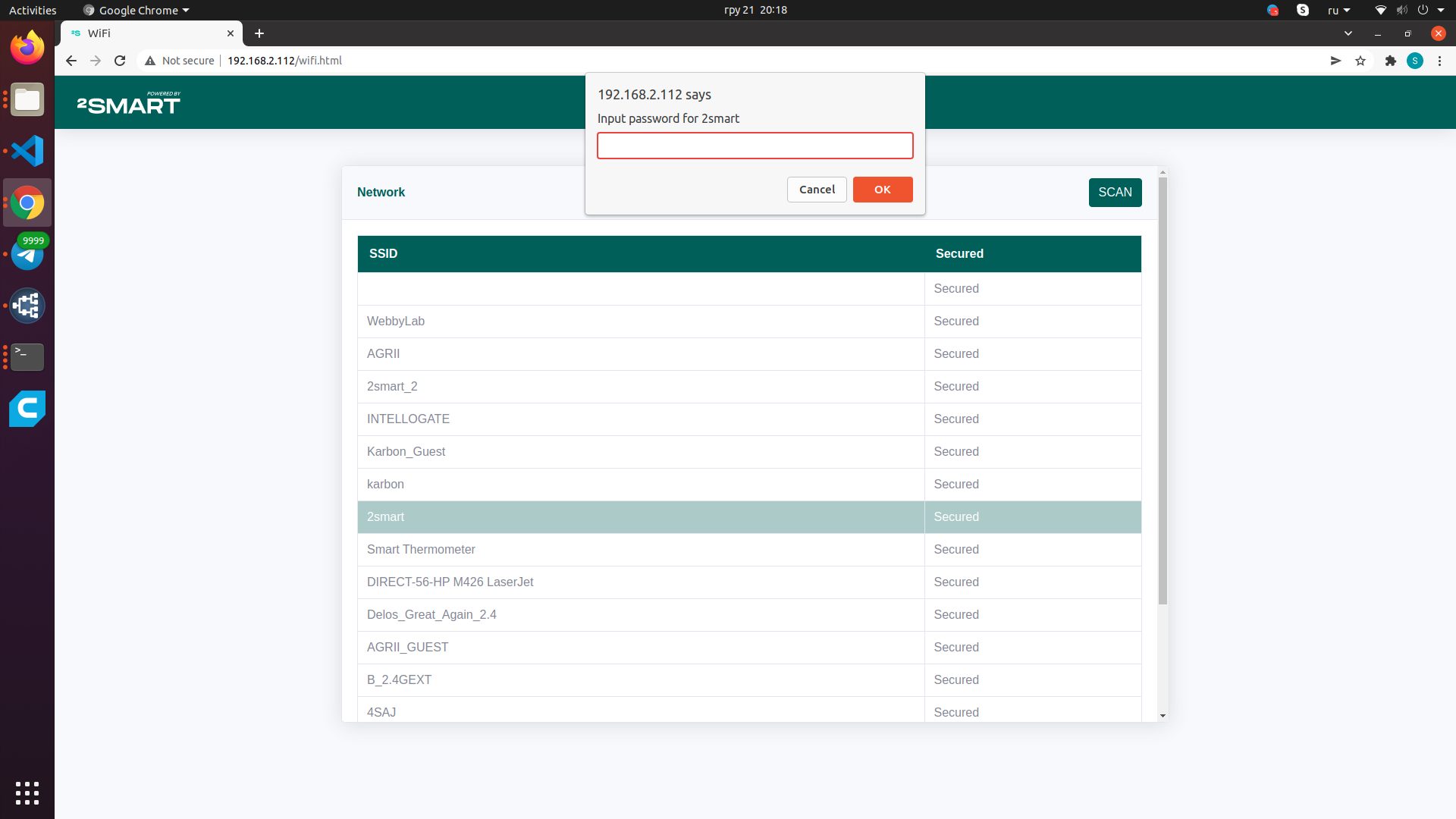
- Wait for the device to reboot. After that, go to the Wi-Fi tab of the web interface, select your network from the list and enter the password. This data is necessary for the blinker to connect to the Internet.
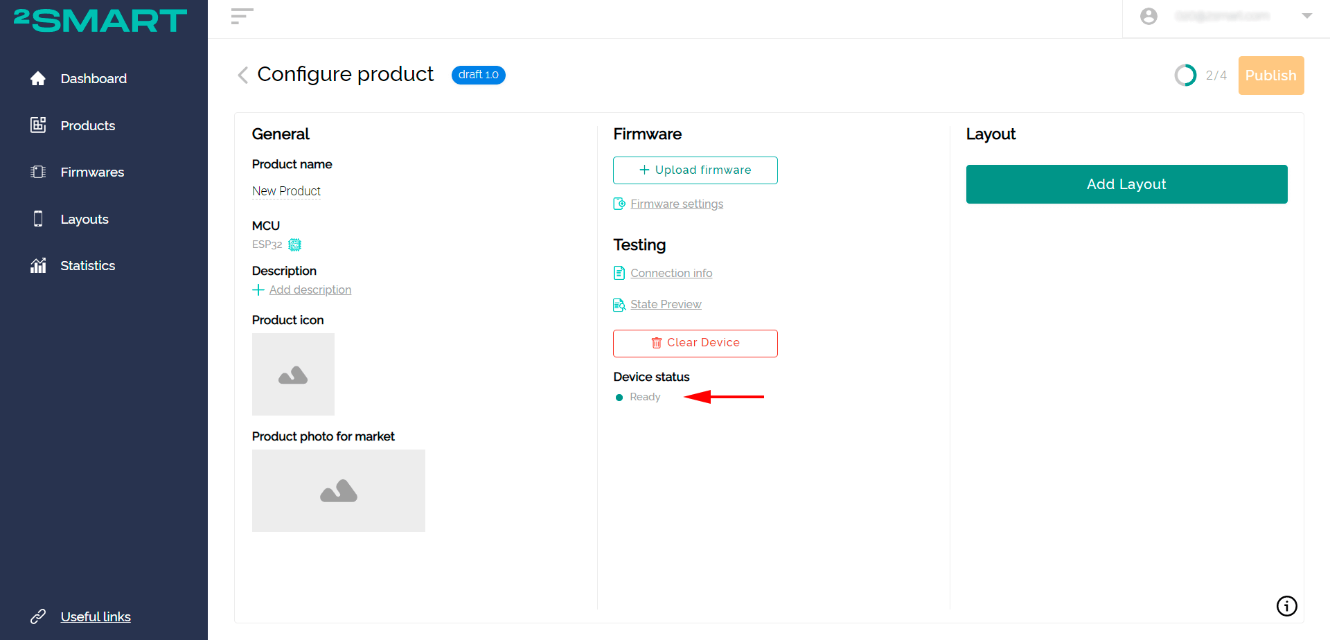
Note! ESP32 devices only support Wi-Fi networks with a frequency range of 2.4 GHz! - Back in your regular Wi-Fi network, you will see the platform device status change to Ready, which means the blinker has connected to the platform.
- Configure the interface of the mobile device management application and check its operability. Read more about these stages of work on the product in the article on connecting to the Wi-Fi relay platform.
- Upload the firmware to the platform and click “Publish” – now the device can be connected to the mobile application according to the standard pairing procedure, it is available to all users.


Conclusions
Each of the reviewed ESP32 firmware development tools – ESPHome and SDK – has its pros and cons. The best option when prototyping is often to take advantage of both bases. ESPHome allows you to quickly validate a device’s concept, while SDK-based firmware provides the most flexible options for fine-tuning its functionality and simplifies the maintenance process.
We are planning to develop both tools on 2Smart Cloud. ESPHome will add features that are missing today, and the SDK will receive new basic abstractions to quickly solve common problems.
Don't forget to share this post!
Read Next

")


Let’s dive into your case
Share with us your business idea and expectations about the software or additional services.
