
Table of contents:
This instruction will help you quickly connect a prototype of a new IoT product to the 2Smart Cloud platform, flash the device, check its performance, and publish a product.
Step One: Creating a new product
2Smart Cloud vendors can use two ways to create a new device: a step-by-step assistant (wizard) and a single page for creating a new product. In the first case, the developer follows the system’s prompts and consistently performs the steps necessary to connect the device to the platform. A similar wizard is used when demonstrating the platform. You have already seen it if you created and configured a virtual lamp after registration.
When using the second method, you can independently choose the sequence of steps, focusing on the functionality available at a particular moment. At the same time, system tips are also available — they are displayed in the lower right corner of the page automatically or by clicking on the information icon.
In terms of functionality, both options are equivalent — vendors can choose either of the two ways that look more convenient for them.
How to create a new product using a wizard
To launch the step-by-step assistant, click the “Create Product” button on the main page of your account.
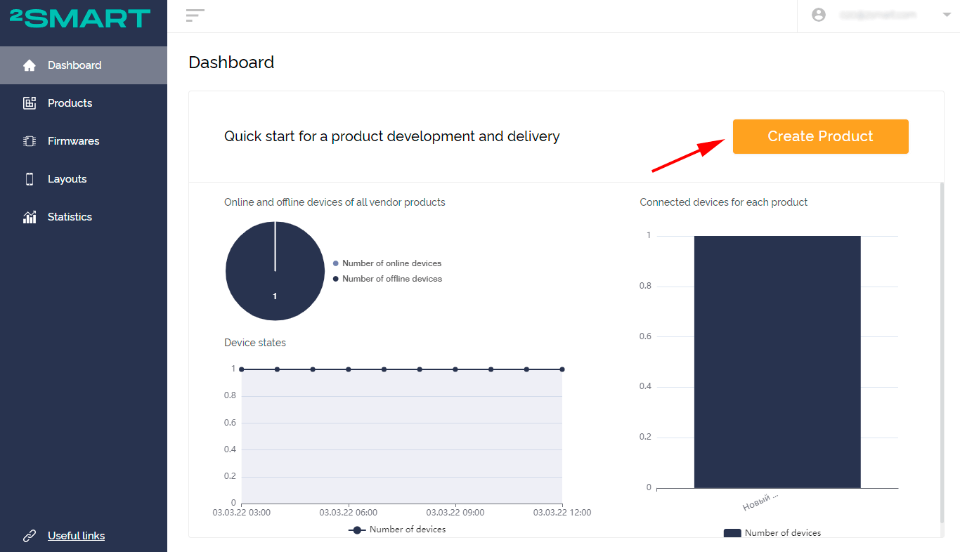
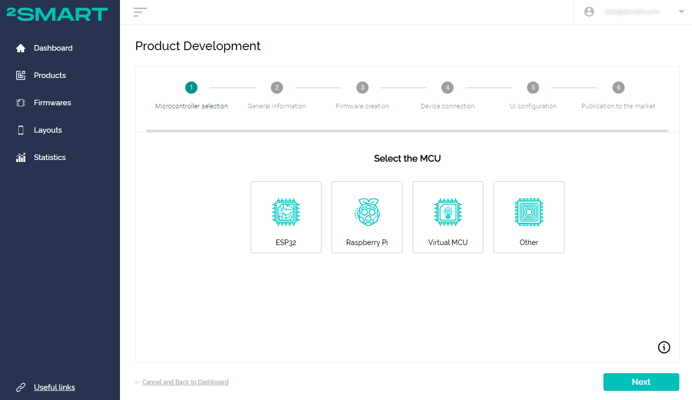
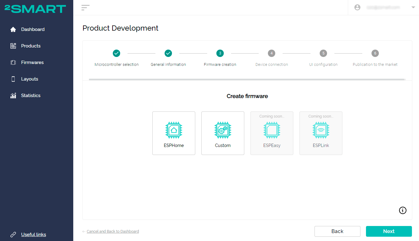
Clicking on this button opens a wizard consisting of six basic steps. The first of them is the choice of a microcontroller, based on which a new product is created.
How to create a new product using the product page
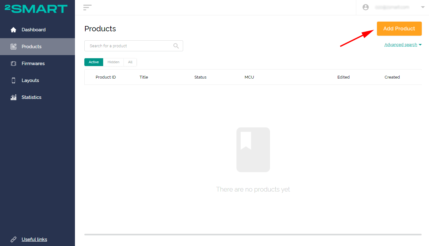
If you want to choose the sequence of steps when creating a new device, go to the Products page. Click on the “Add Product” button.
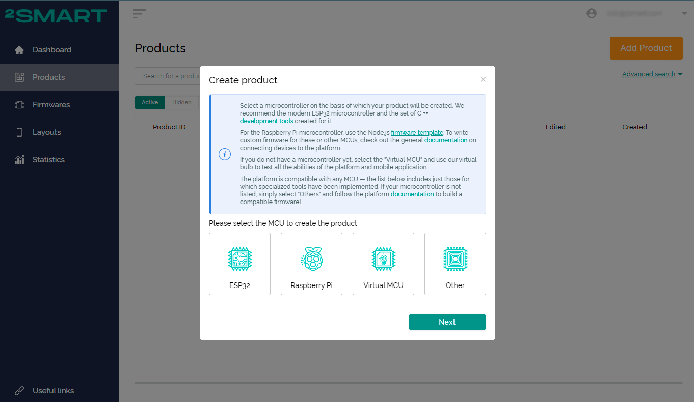
The microcontroller selection window will appear. Select the MCU that your product prototype is based on and click Next.
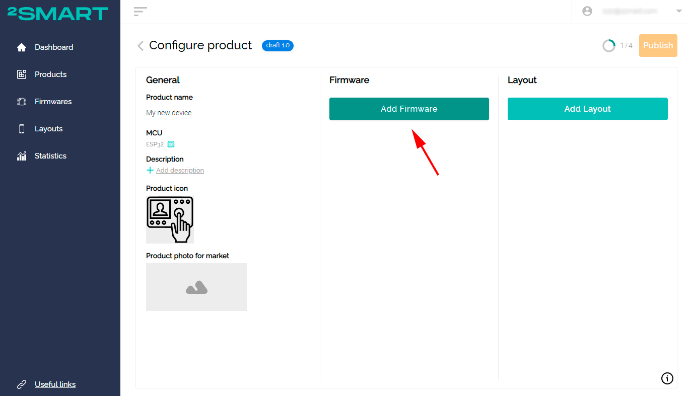
You will see a Configure product window. The progress indicator in the upper right part of the screen will help you figure out what steps you need to take to complete the process of connecting the device to the platform.
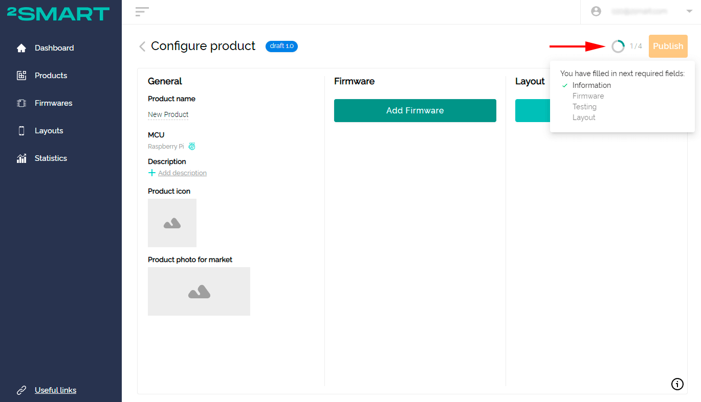
You can choose any sequence of steps while working on the device. At the same time, some stages may be unavailable and activated during work — for example, you cannot customize the interface of a mobile application until you connect the prototype to the platform.
Is it possible to pause work on the product temporarily
You can pause the work at any time — the changes will be saved automatically. To resume work, navigate to the Products page and select your device.
The only limitation is that you will remain on the product page, even if you used the step-by-step assistant initially.
Step Two: General product information
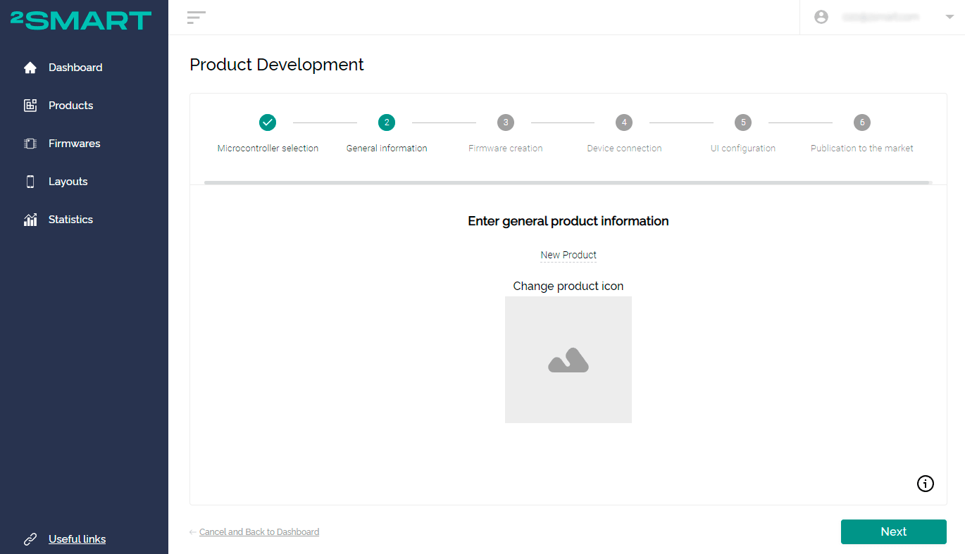
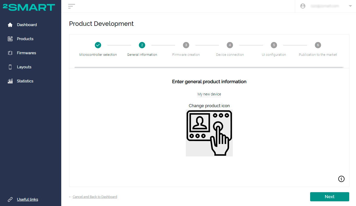
Having chosen the microcontroller based on which your device was created, we recommend that you immediately fill in the general information about the product. Specify the name of the device and upload the icon in .svg format.
When working with a wizard, this is the second step of the assistant:
On the product page, device information can be entered in the “General” column on the left:
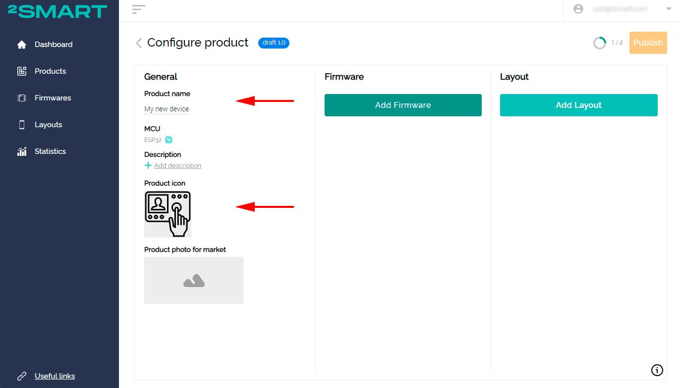
You can skip this step, but you should return to it before publishing the product on the platform. We recommend you to fill in all the fields, as they are displayed in the device catalog of the 2Smart Cloud mobile application. This is the information that end-users will see, and it should pique their interest in the product.
- Product name: the name under which the device will be displayed in the mobile application market.
- Description: a short description of the product displayed on its card in the market.
- Product icon: a graphic image that accompanies the product name in the market.
- Product photo for market: a photo of the device accompanying the text description in the platform market.
Step Three: Creating the firmware
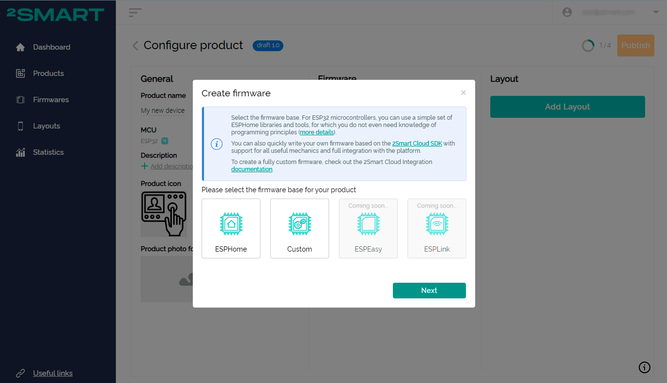
When working in the step-by-step assistant, you will automatically see the window for selecting the base for the firmware by clicking “Next”. There are currently two options available for the ESP32 microcontroller: ESPHome and Custom (details on the differences between these bases). For other microcontrollers, only the Custom base is available.
To create firmware on the product page, click the “Add Firmware” button, and a similar window for selecting the firmware database will open.
Further steps to work on the product depend on the choice of the firmware base.
For the ESP32 microcontroller they are as follows:
An ESPHome platform is a simple tool for creating the firmware of the ESP32 microcontroller, which does not even require knowledge of programming principles. This is its main advantage. Initially, ESPHome was designed for home automation systems, so it is not suitable for creating commercial devices by default. In particular, the standard ESPHome firmware implies that the credentials of the home Wi-Fi network must be pre-wired into the code.
However, 2Smart Cloud vendors can take advantage of ESPHome and not worry about its disadvantages. When creating firmware on this base, a simple ESPHome syntax is used. However, the production firmware, installed on the entire batch of devices, does not contain Wi-Fi credentials. The user transmits the parameters of his network when pairing the device with a mobile application – as for firmware written using standard tools.
Please note that ESPHome-based firmware in 2Smart Cloud is assembled on the platform servers. You do not need to use assembler programs on your computer.
The firmware of the test device and the production firmware of ESPHome: what is the difference
When using the ESPHome tool, vendors will note that in 2Smart Cloud, they will be offered two firmware options: test and production.
The difference between these two options is evident from the name. The test firmware is intended solely for testing the functionality of the prototype. Conceptually, it is closer to pure ESPHome – the developer’s Wi-Fi network credentials are sewn into the code, which must be specified when assembling the firmware on the platform. This is necessary to quickly connect the prototype to the platform and continue working on the product.
Production firmware is the code version that needs to be installed on the entire batch of devices. There will no longer be Wi-Fi network credentials, and users will specify them at the pairing stage.
The code describing the device’s logic using ESPHome is similar in both cases.
How to create a firmware based on ESPHome
Use the documentation and ready-made examples on https://esphome.io/ and other sources to write code.
After writing the code for your product, return to the platform:
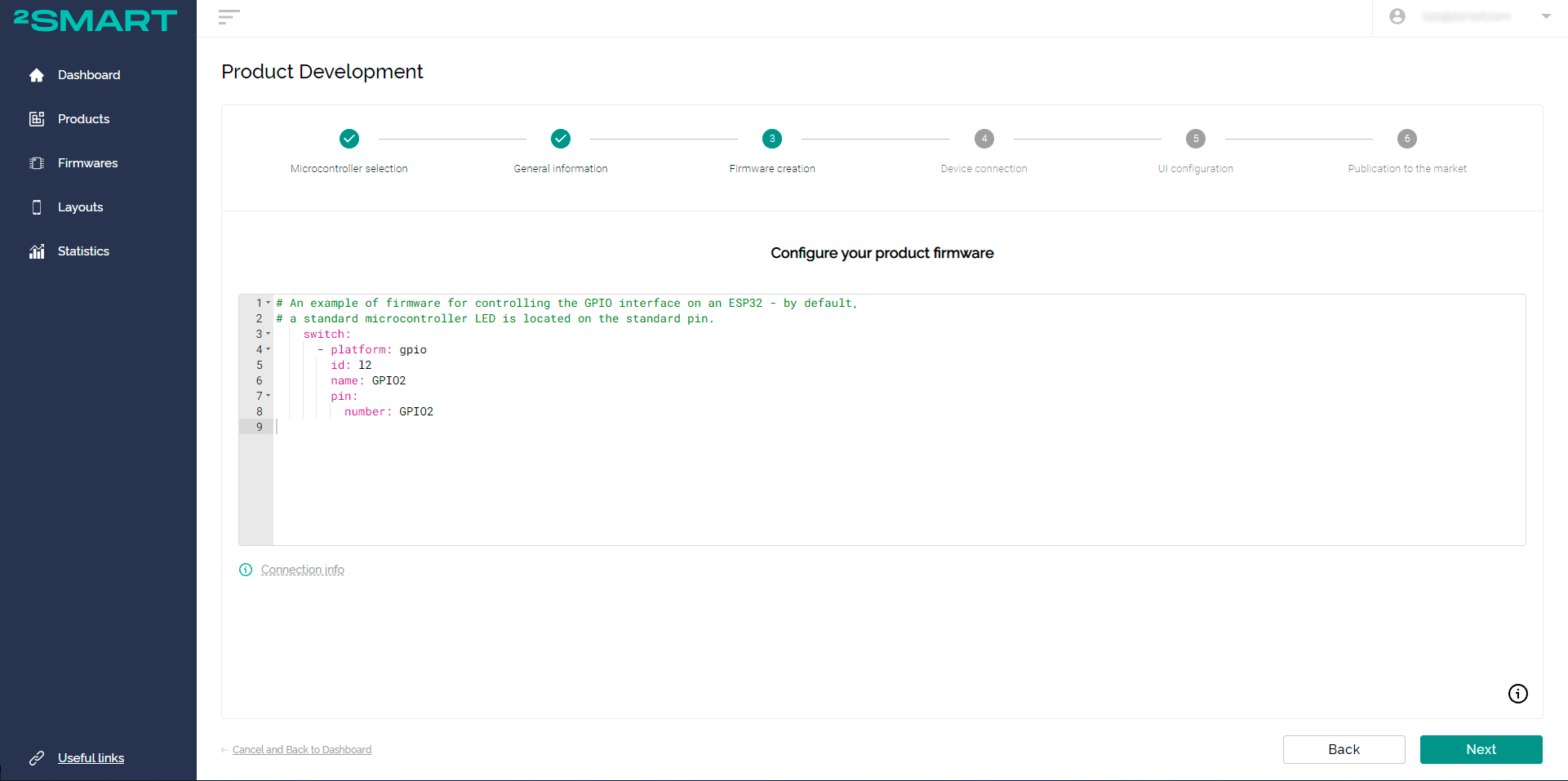
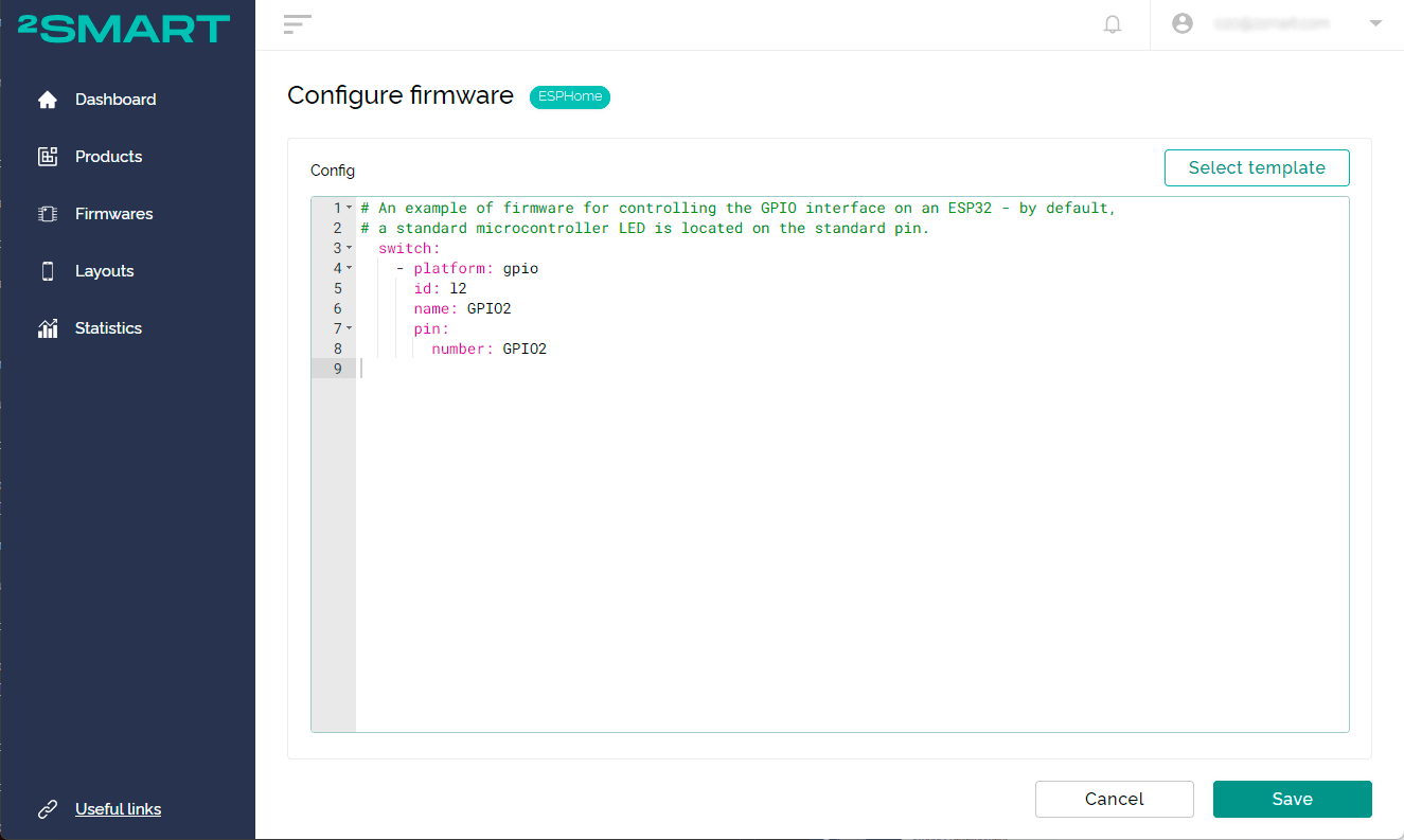
- Paste the ESPHome-based firmware code into the edit window.
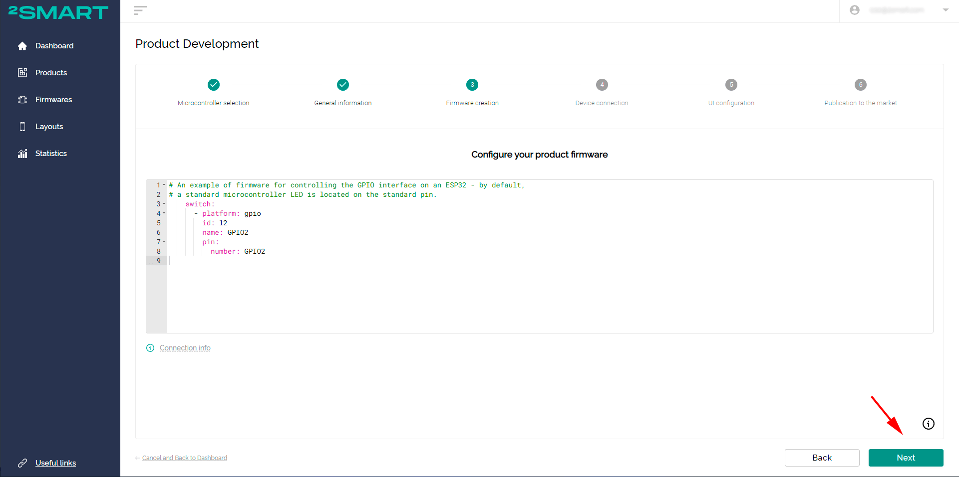
When using the step-by-step assistant, this is the third stage of working on the product. The editor opens automatically:
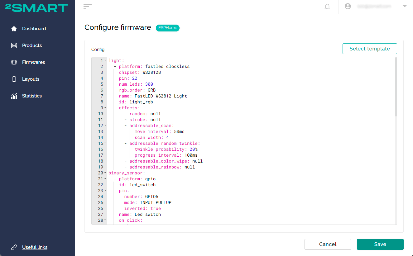
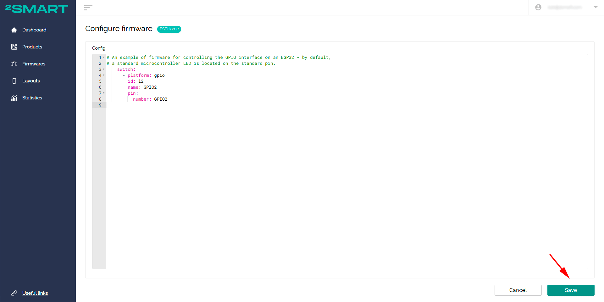
 When using the product page, a similar window opens after selecting ESPHome as the firmware base:
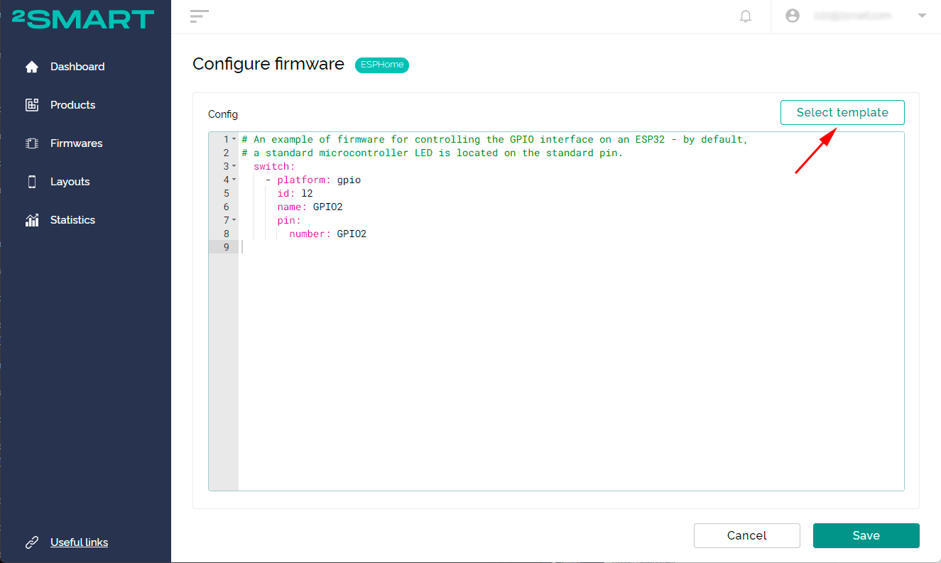
 You can use ready-made templates with ESPHome firmware for several simple devices.
- Click the “Select template” button.
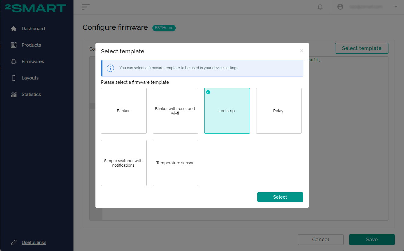
- Choose a template and click the “Select” button.

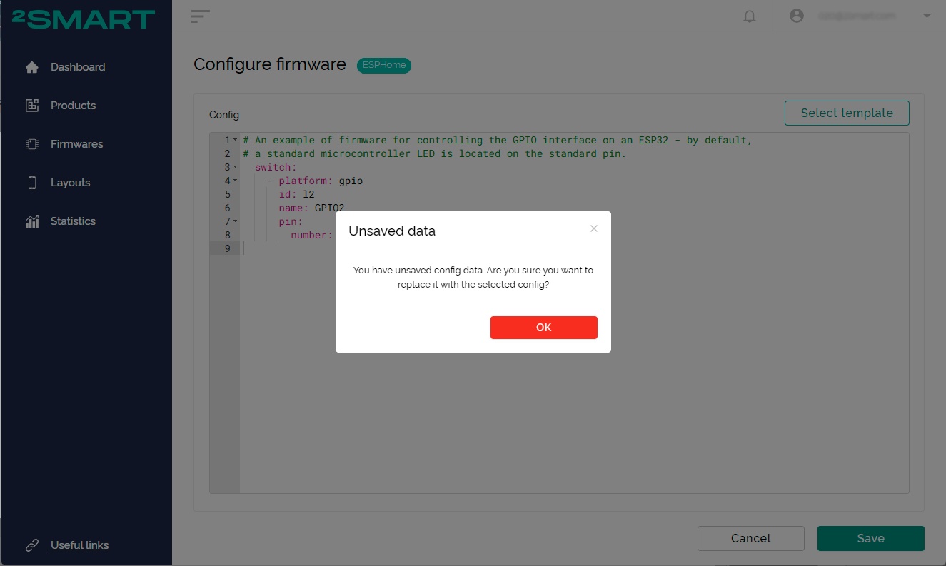
- Confirm that you want to replace the current configuration with the template.
- Use the template as is, or make the necessary changes.

- Click the “Select template” button.
- Save the code.
Click “Next” in the step-by-step assistant:
Click “Save” when using the product page:

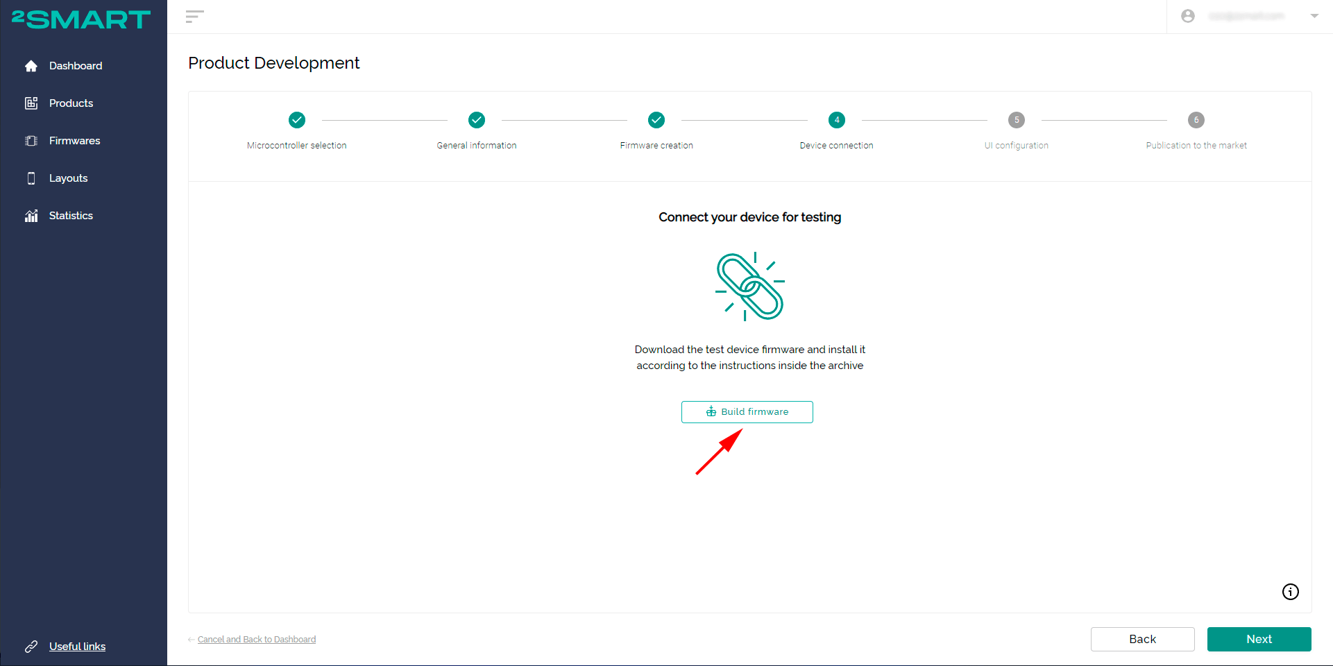
- Build the test firmware.
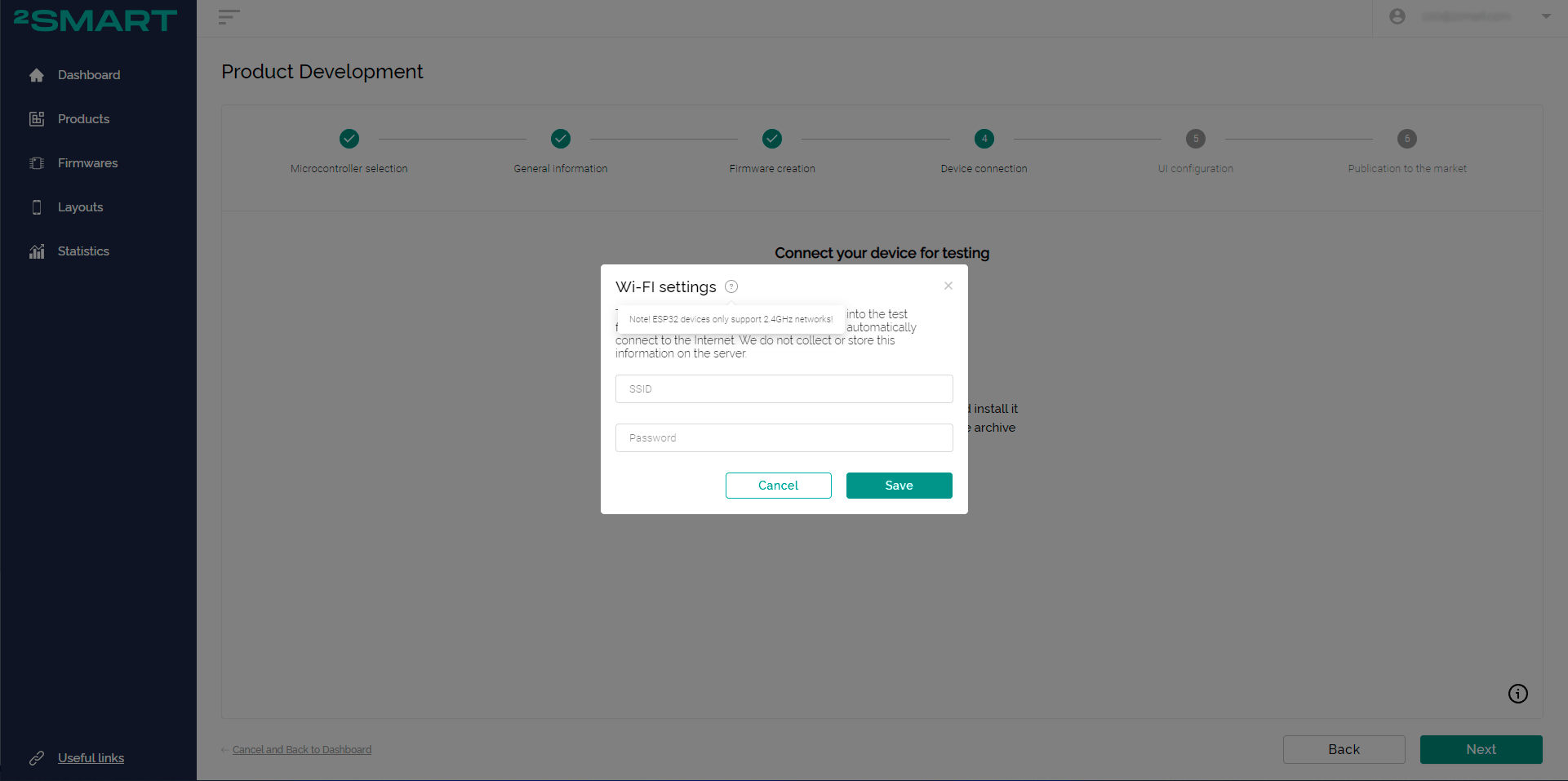
When using the wizard, click “Build firmware” in the next step.
Specify the credentials to connect to your Wi-Fi network:
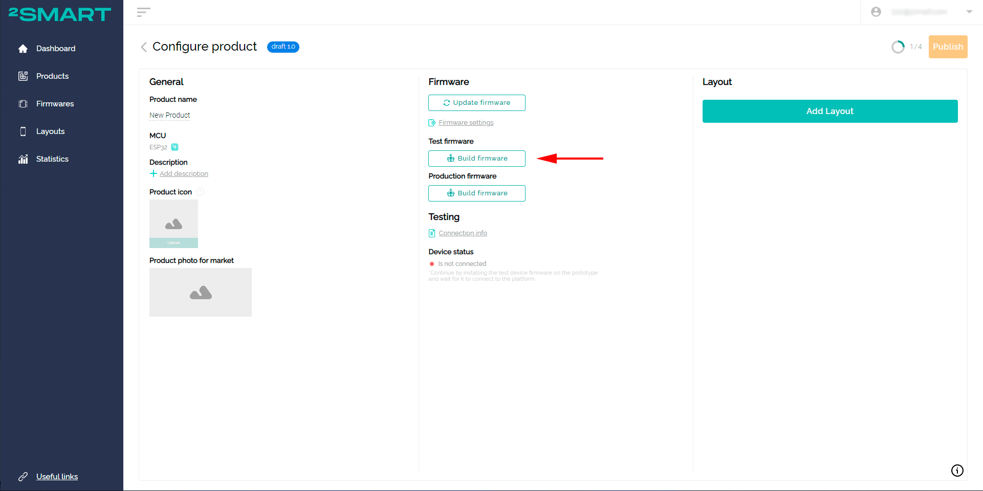
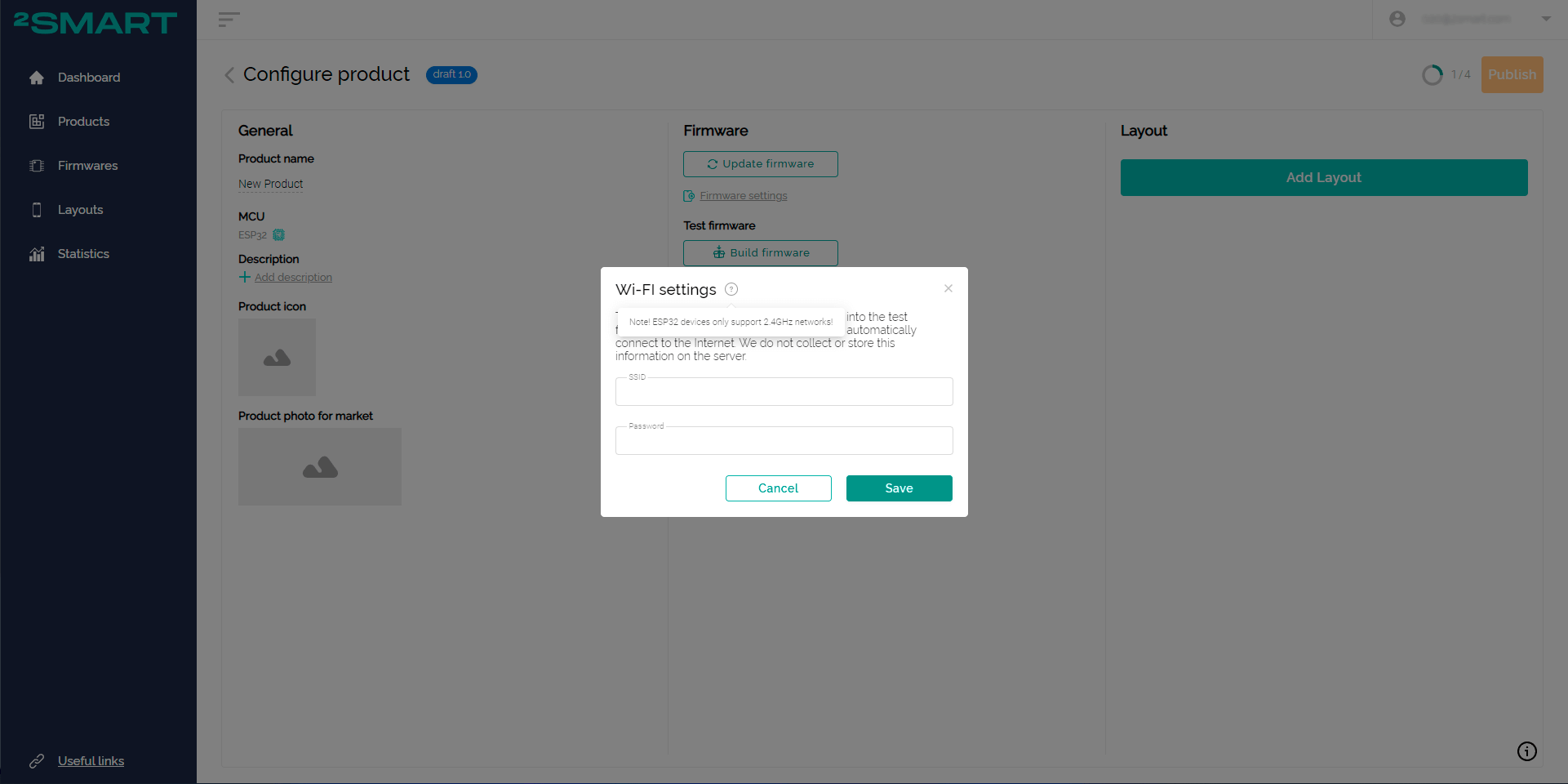
When using the product page, click the first of the two “Build firmware” buttons.Specify the credentials to connect to your Wi-Fi network:
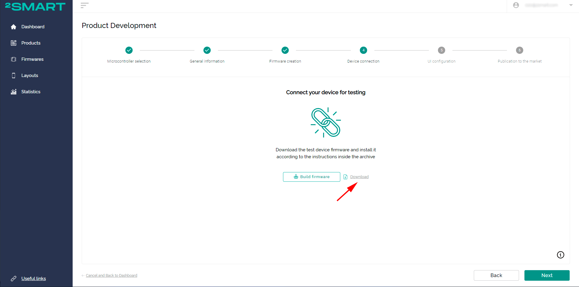
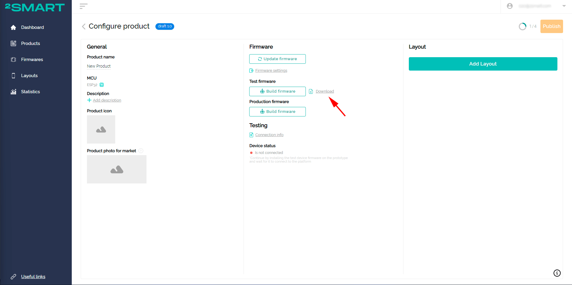
- Download the archive with the test firmware. Click on the download link next to the “Build firmware” button.In the step-by-step assistant:

On the product page:
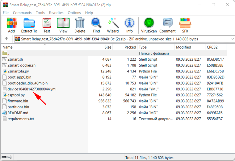
- Flash the prototype using the instructions in the readme.md file inside the archive or illustrated instructions on our blog:
Please note! If the firmware is already written to the microcontroller, do not forget to remove it according to the documentation.

Pay attention to the device[ID].yml file in the test firmware archive! It contains the ESPHome firmware configuration of your device. If you need to edit the firmware configuration at the prototype testing stage, it is unnecessary to do it on the platform and build a new archive. In such cases, follow the simple instructions:
- edit the firmware configuration and make the required changes to the device[ID].yml file;
- install updated firmware on the device;
- repeat the previous two steps if necessary;
- copy the final config to the platform before building the production firmware.
The Software Development Kit (SDK) developed by the 2Smart Cloud team is the most functional tool for writing firmware for ESP32 microcontrollers. The firmware functionality created on such a base is much more comprehensive than in the case of ESPHome. In addition, the development of the SDK is a higher priority for the team, so all new features of the platform will primarily appear in this base. This means that developers who have chosen the SDK firmware option will be able to use the innovations of 2Smart Cloud in their products faster.
The basic principle of the SDK-based firmware is that the code for integrating the device with the platform has already been written. It is enough for the developer to describe the logic of his product.
How to create SDK-based firmware
Use the documentation in the 2Smart Cloud Github to write the code. Pay attention to the ready-made SDK-based firmware examples, use them as firmware templates for your devices, and change and modify the code as you need.
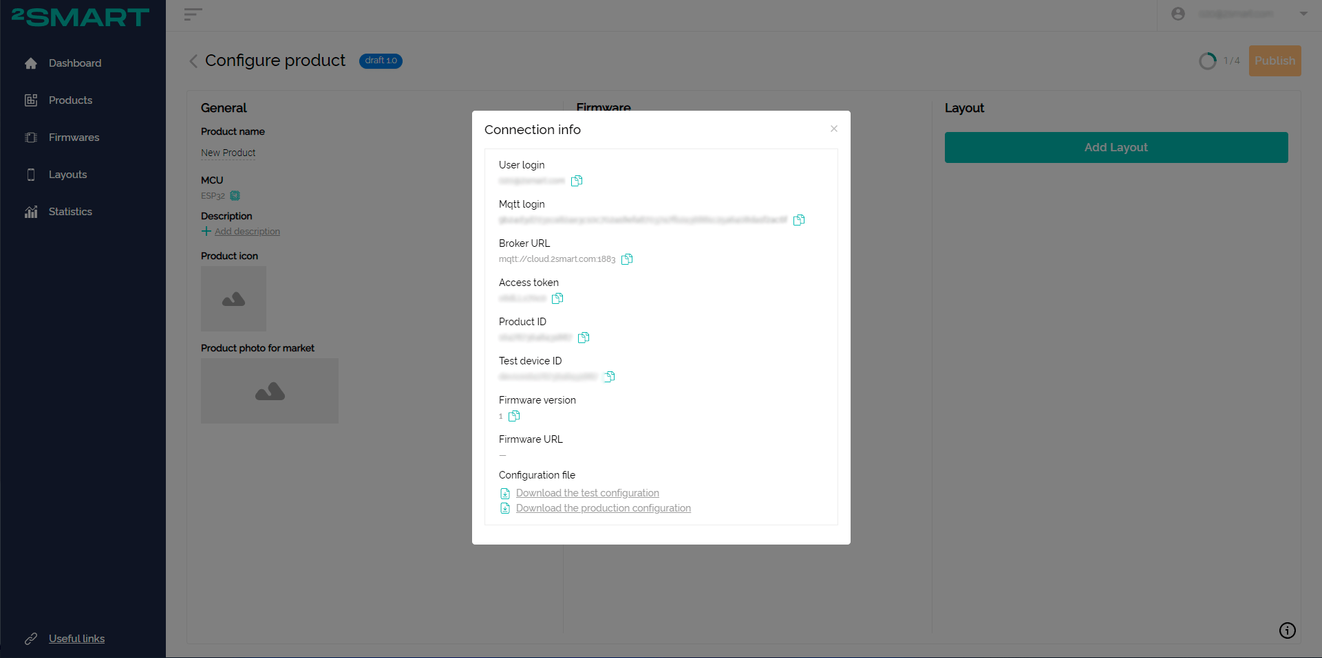
- Specify the data required to connect to the platform in the firmware code of your device.
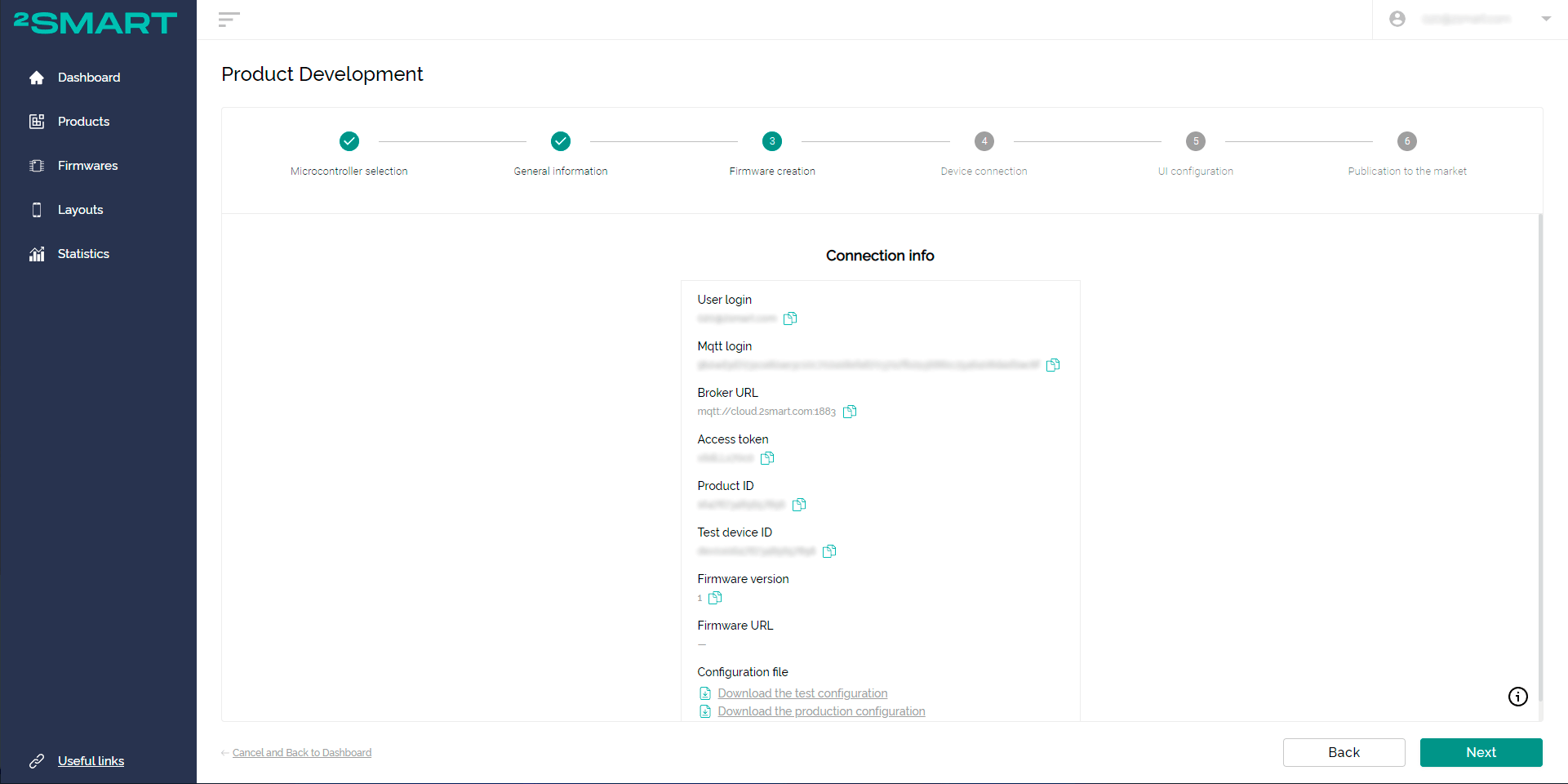
When using the step-by-step assistant, the data is automatically opened when selecting Custom firmware:
When using the product page, click on the “Connection Info” link:
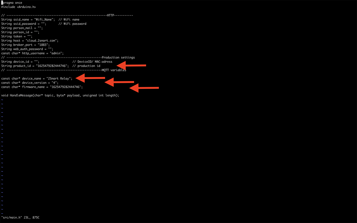
- Go to the downloaded firmware repository, open the Firmware/src/main.h file and make the following changes:
- copy the Product ID and paste it into the firmwareName and ProductID fields,
- enter the name of your device’s hotspot instead of the default one in the device Name field,
- if you are creating a new product, make sure that its version specified in device_version equals 1.

- Save the changes in the firmware code and use it to flash your device.
Please note! If the firmware is already written to the microcontroller, do not forget to remove it according to the documentation.
- After successful flashing, the device will open a Wi-Fi hotspot with the same name specified for the device in the firmware code. Connect to this network.
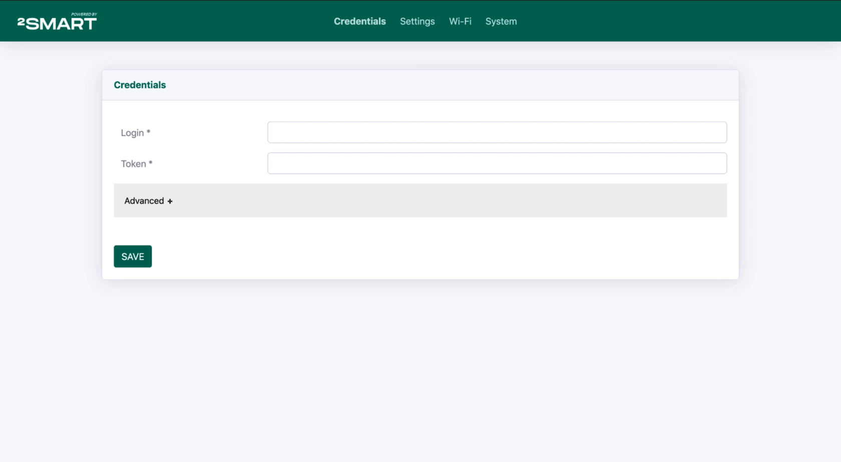
- Follow the link http://192.168.4.1/ to open the device’s web interface. Use the login “admin” and password “admin” to log in (if necessary, you can change the default values in the settings).

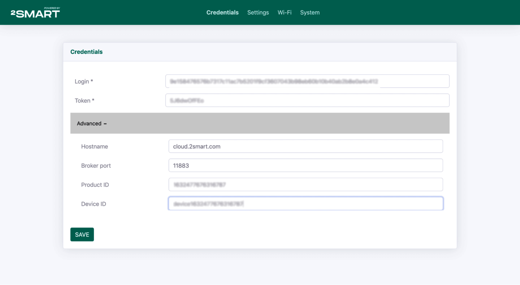
- Copy the values from the “Connection Info” window to the fields on the Credentials tab:
- in the Login field – the “User login” value,
- in the Token field – the “Access token” value,
- in the Hostname field (under the Advanced spoiler), enter the value “cloud.2smart.com ”,
- in the Broker port field, enter the value “11883”,
- copy the “Test device ID” value in the Device ID field.
After filling in all the fields, click Save.

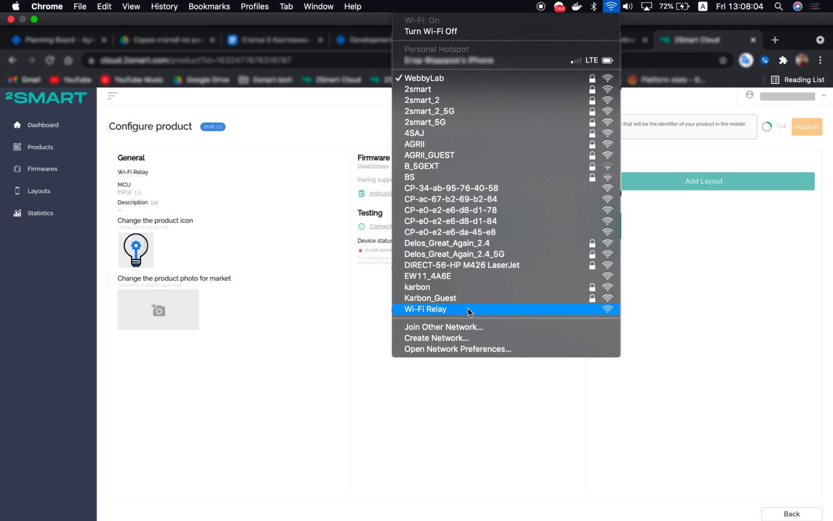
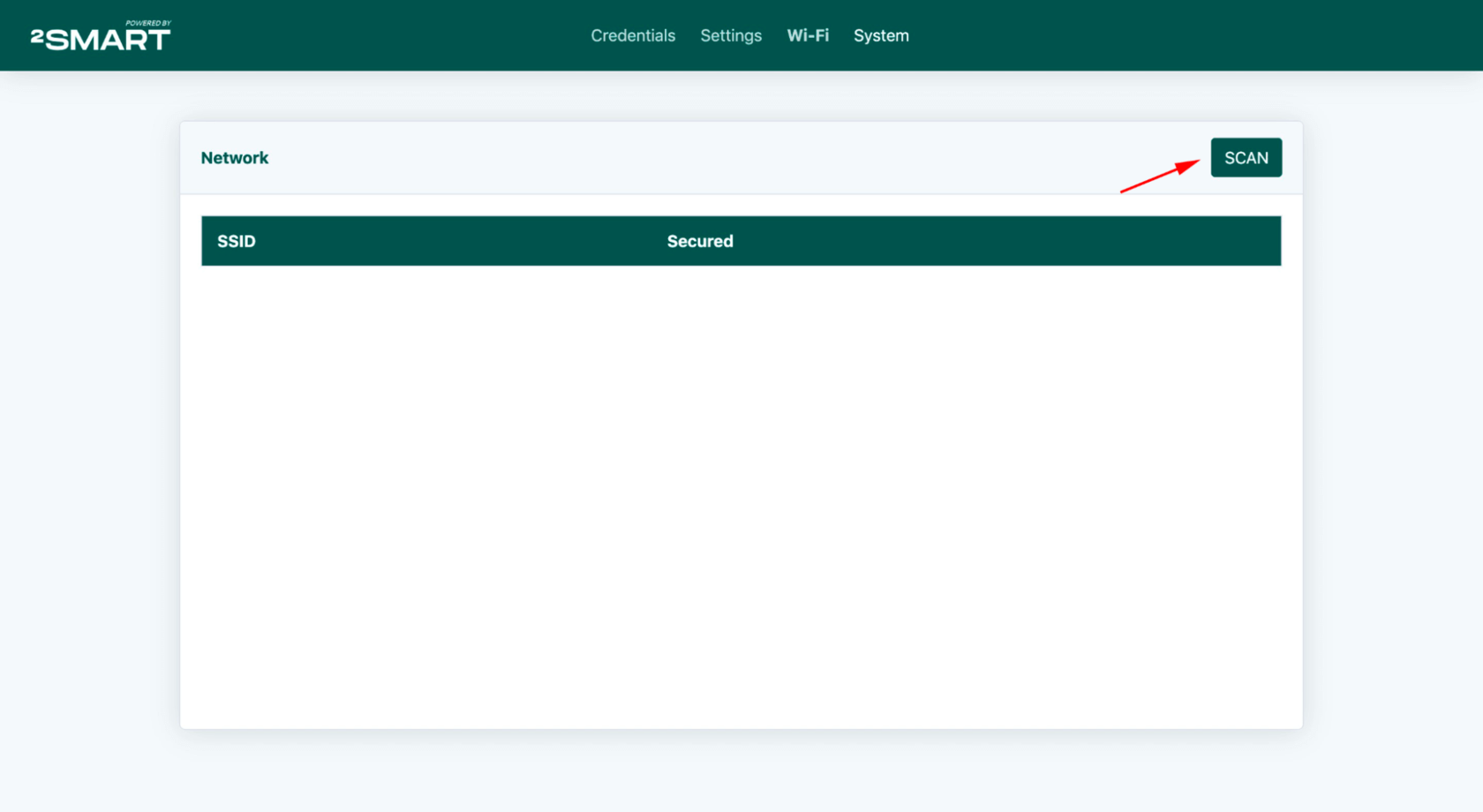
- Make sure your computer is still connected to the device’s Wi-Fi hotspot. Go to the Wi-Fi tab and click Scan.
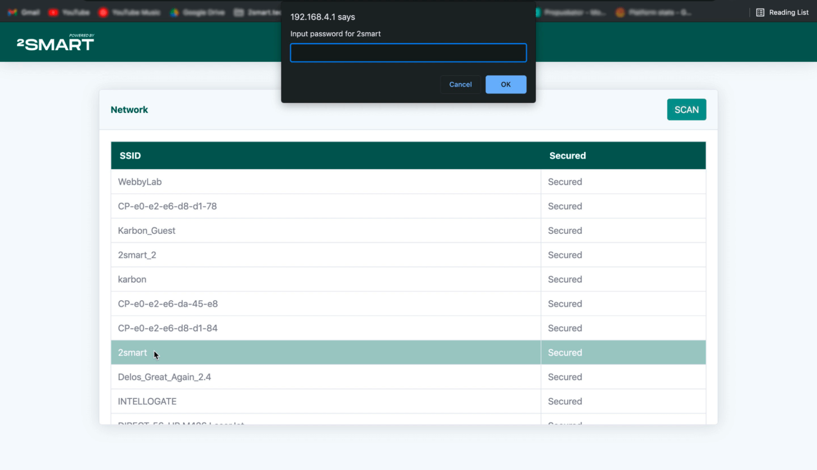
- Select your Wi-Fi network from the list and enter a password to access it. This is required for your device to connect to the platform.
Please note! ESP32-based devices support only Wi-Fi networks with a frequency range of 2.4 GHz!


For other microcontrollers, use the documentation for creating firmware in the 2Smart Cloud GitHub.
Step Four: Connecting the device
After creating the firmware, install it on the device. Your prototype should automatically connect to the platform.
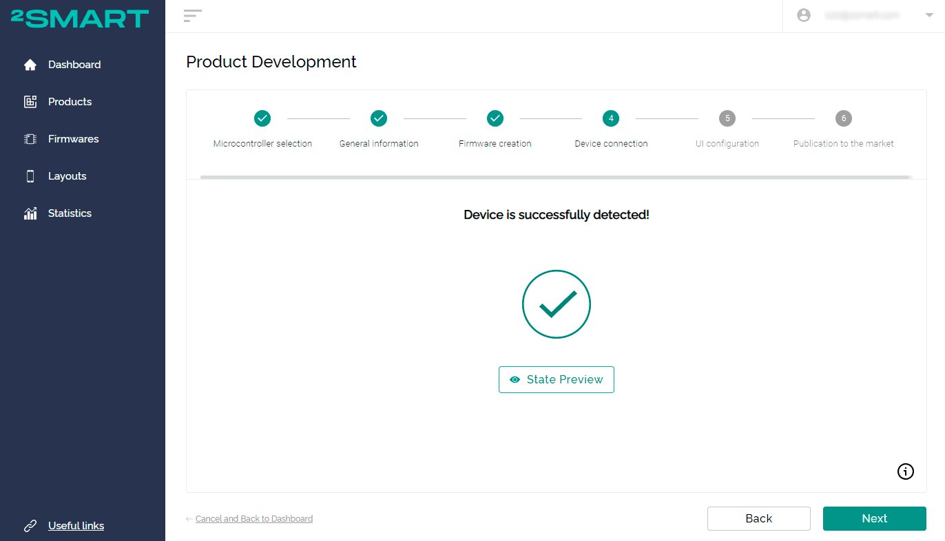
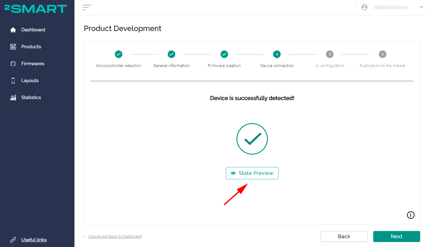
If you are creating a device using a wizard, go to the fourth stage of product development by clicking “Next”. Once the device is detected, you will receive a notification.
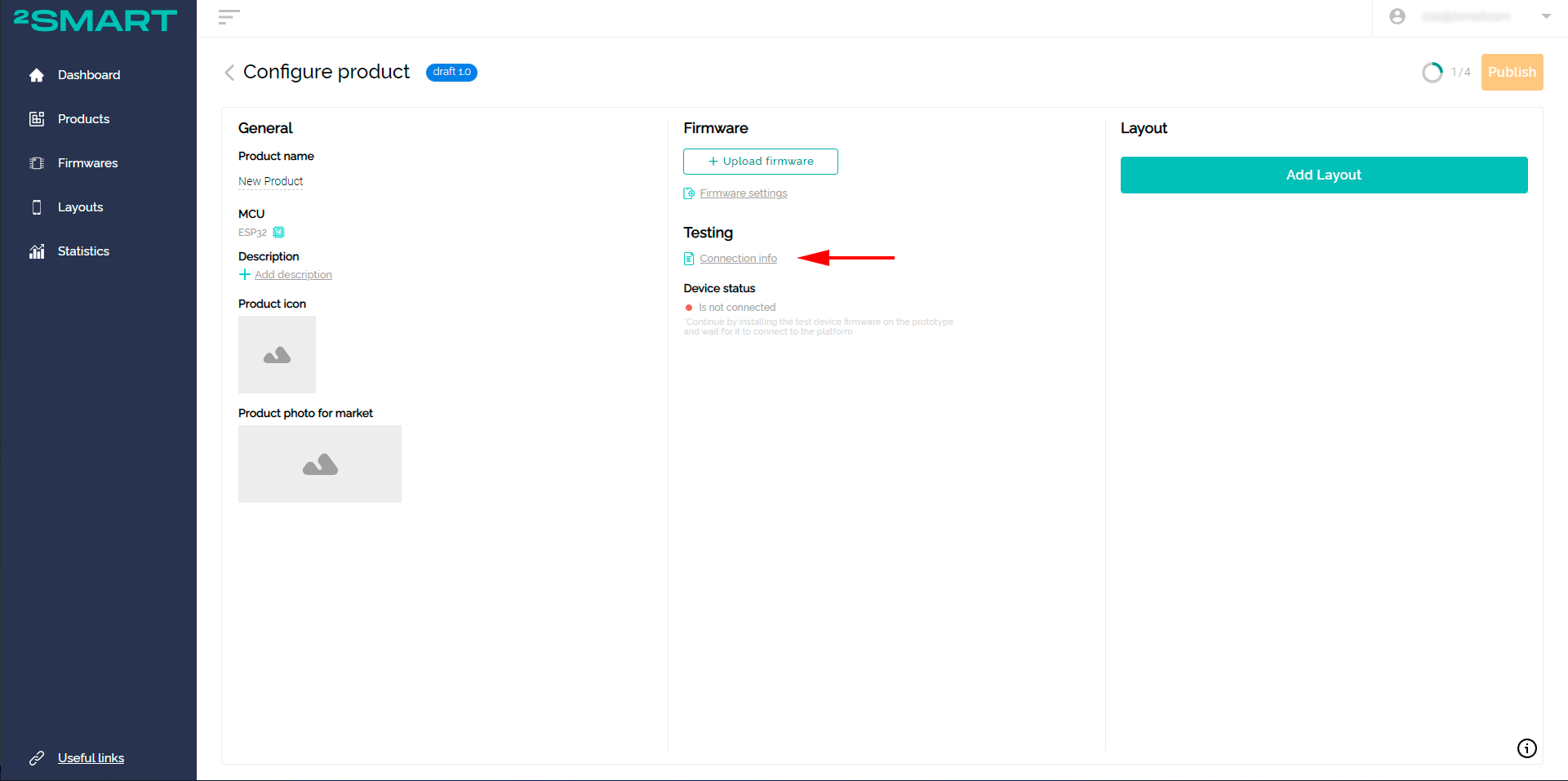
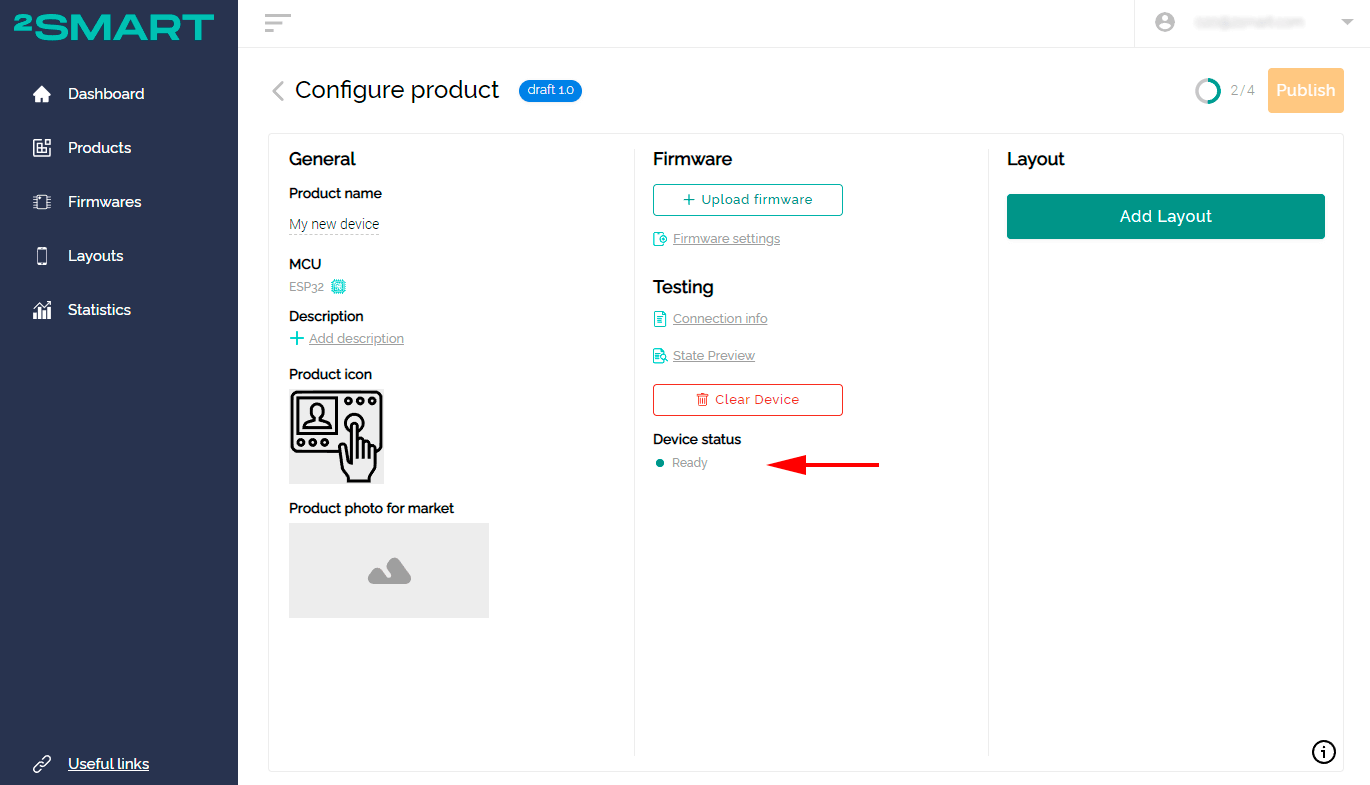
When using the product page, pay attention to the “Device status” field. After connecting the prototype to the platform, the status will change to Ready.
If the device does not connect within one to two minutes, try unplugging it from the power supply and plugging it back in. If this does not result, check whether you have correctly followed the instructions for flashing the prototype.
Let’s collaborate
We’re empower your business with our technology expertise
Step Five: Mobile application interface
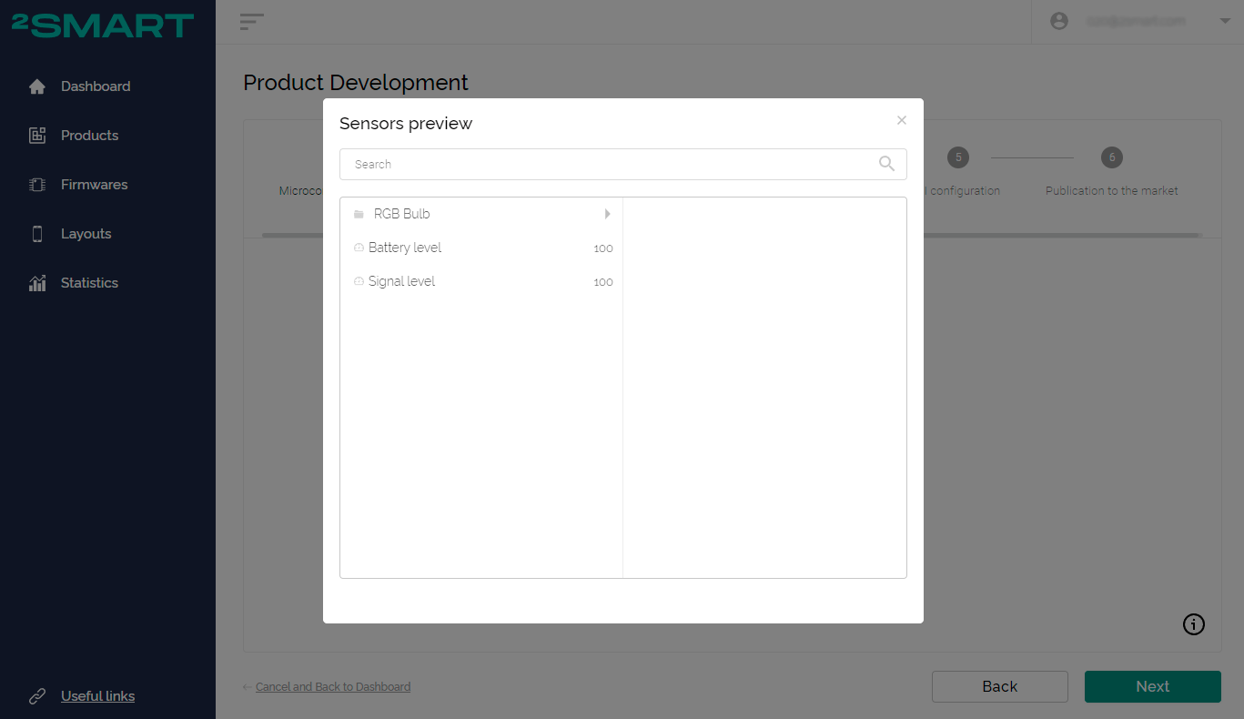
After connecting the prototype to the platform, the data of all device sensors will be available.
The “State Preview” button will appear in the step-by-step assistant:
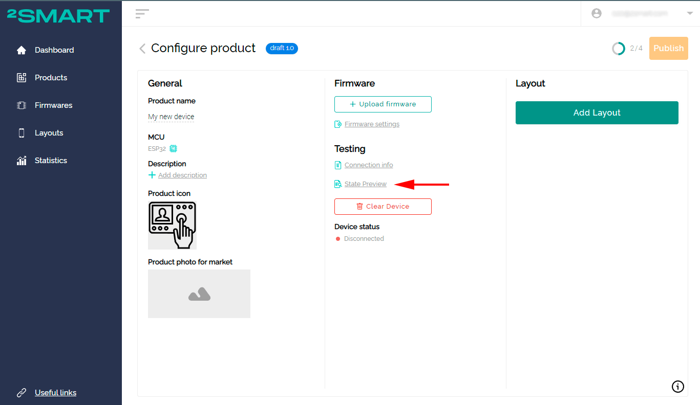
On the product page you will see a similar link:
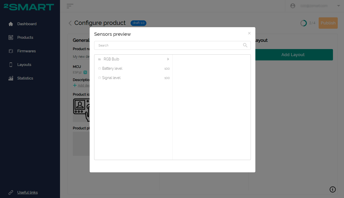
Now you can configure the mobile application to control the device.
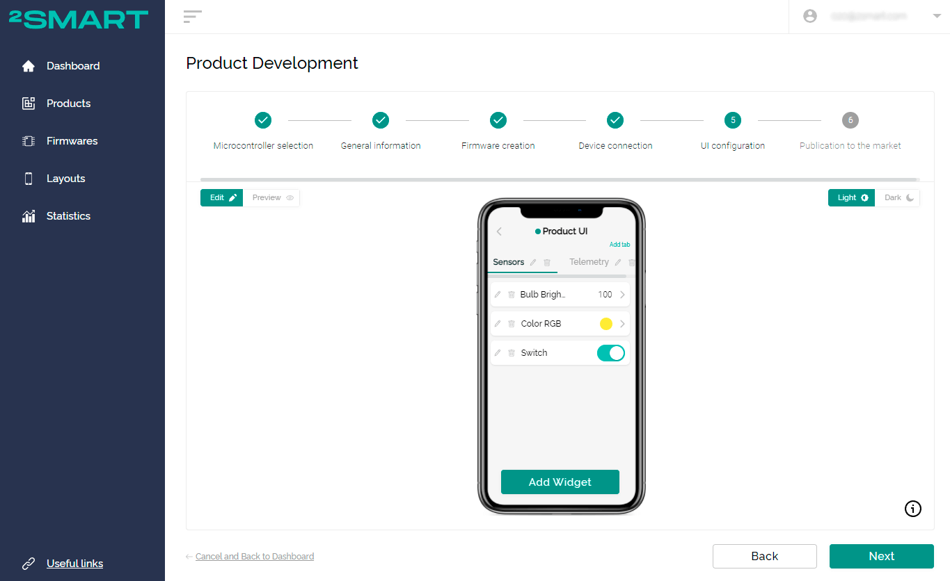
When using the wizard, configuring the application is the following fifth stage:
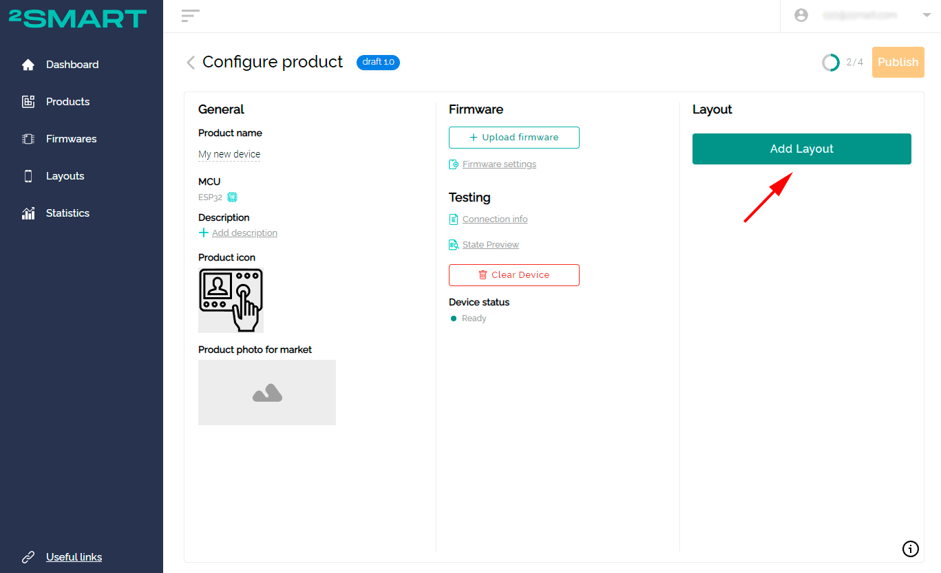
When using the product page, click on the “Add Layout” button:
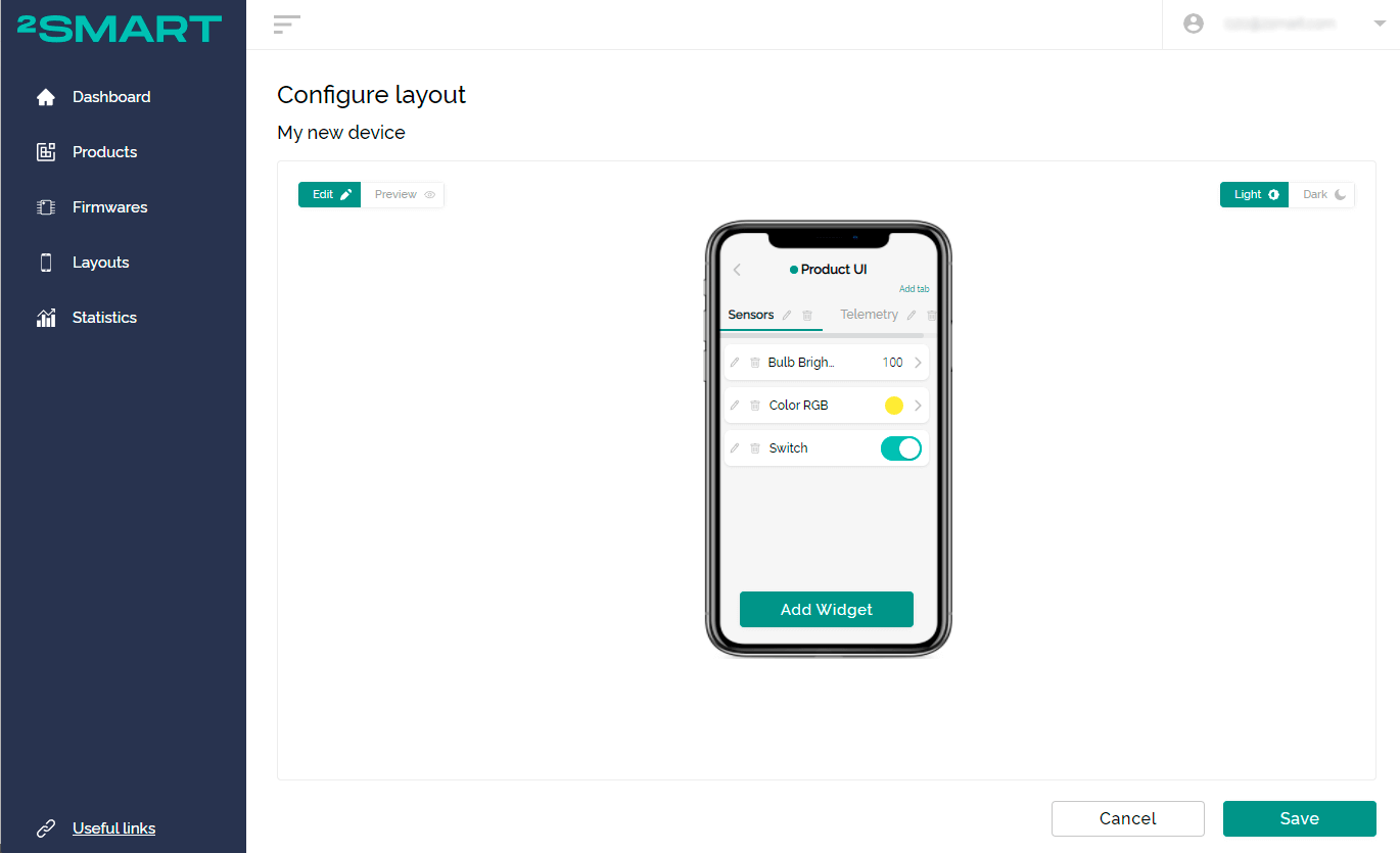
Having received information about all sensors, the platform will automatically create an application interface. A control widget will be offered for each of the sensors.
Since different widgets can be used for the same device sensor, we recommend that you configure the interface manually. Use the 2Smart Cloud widget library and set the most convenient widget for each sensor. A detailed description of each of the widgets can be found in the help.
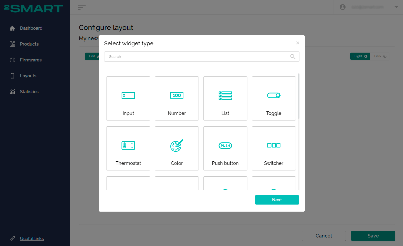
Click “Add Widget” in the mobile app emulator to access the widget library.
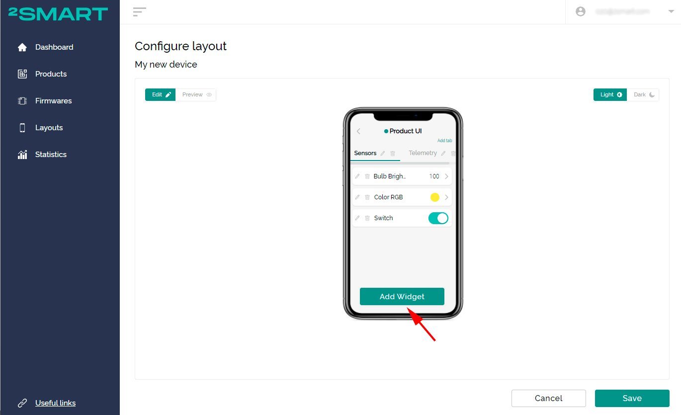
You can also:
- delete existing widgets;
- rename existing widgets;
- change the order of widgets using the drag-and-drop function;
- group widgets using tabs.
Step Six: Testing the prototype
Please note that you can remotely control the prototype when configuring the mobile application interface. The emulator on your monitor screen is interactive. The device responds to all commands, as when using a real mobile application.
However, we recommend that you test control of the prototype from a real mobile device. After configuring the interface, download the 2Smart Cloud mobile application and log in with the same credentials you used when registering in the developer’s account. Your new product is already listed on the “Devices” screen marked “Test”.
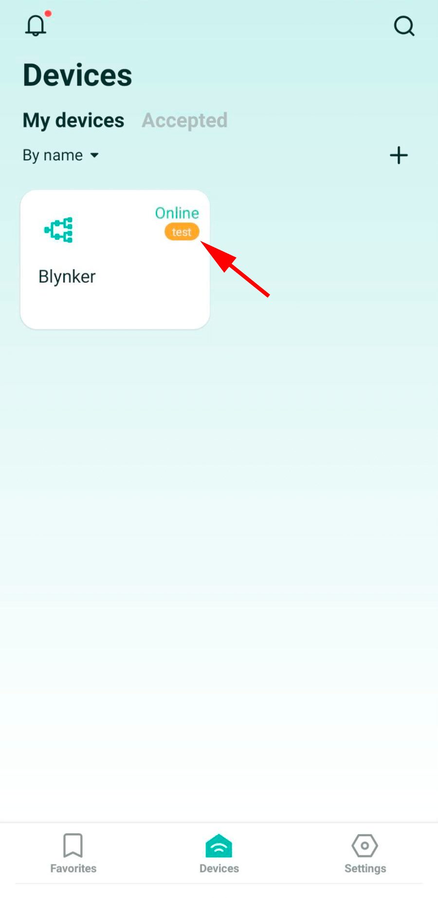
If you already have the 2Smart Cloud app installed and don’t see the device in the list, restart the app.
Ascertain that your prototype is properly managed via the mobile application. Take note of the usability of each widget. Return to your account if necessary, select another widget to control a specific device function, and rearrange the widgets on the application screen. Restart the app on your smartphone to see the changes take effect.
After testing the device, return to your account to complete the last step — publishing your product on the platform.
Step Seven: Publishing the product
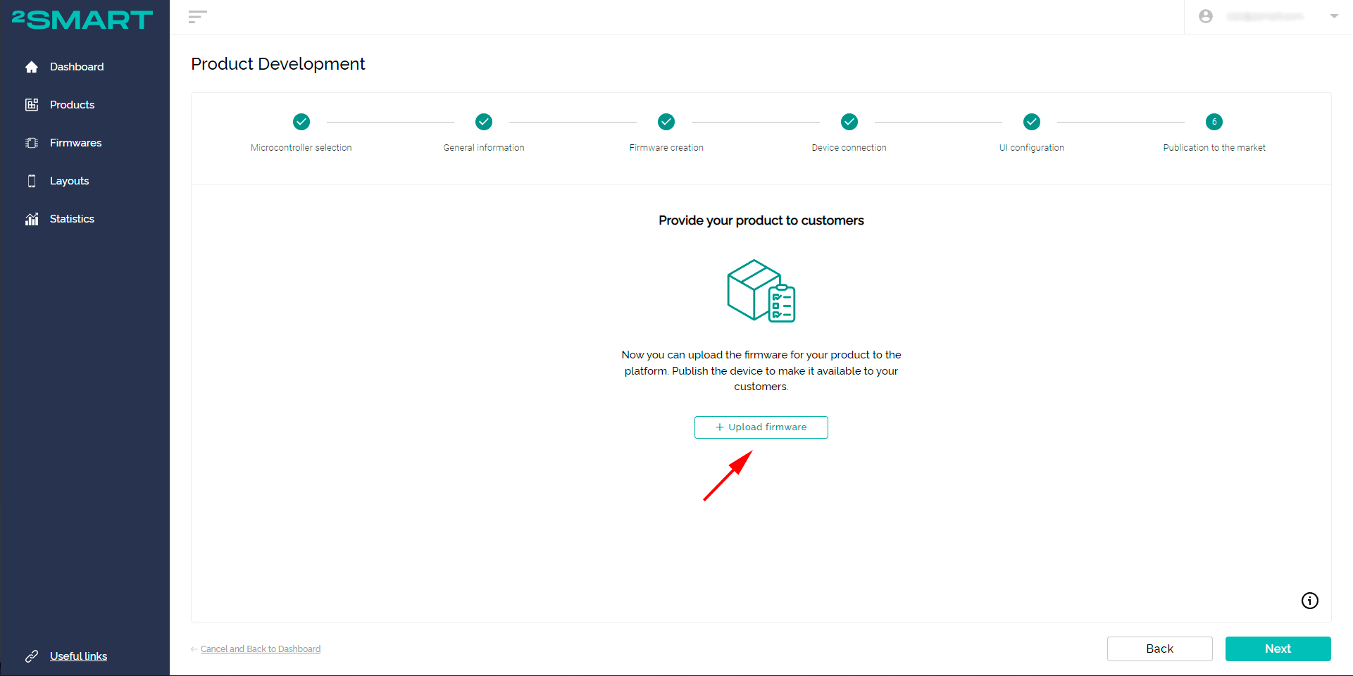
The final stage is the publication of the product on the platform. When using custom firmware, you need to upload the firmware file to the server. This is necessary to update the entire batch of your devices over the air. If the firmware is based on ESPHome, such a step is not needed.
When using the wizard, the “Upload Firmware” button will appear at the last stage:
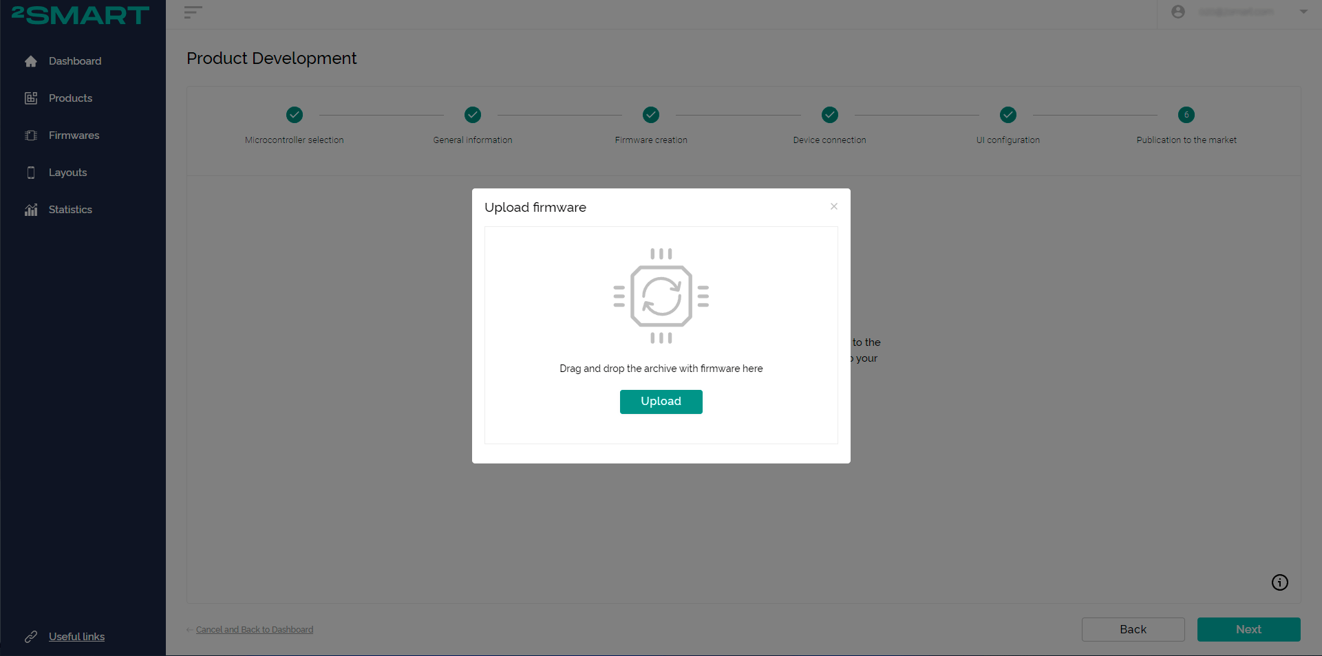
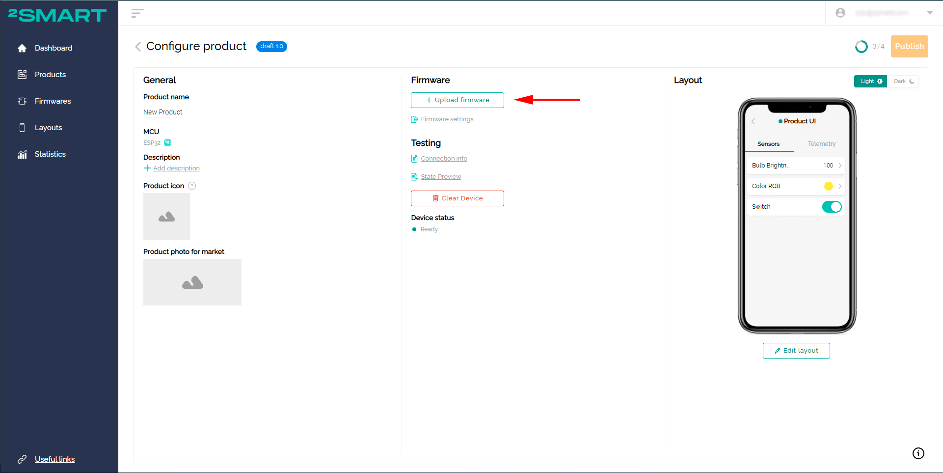
On the product page, a similar button is located in the “Firmware” field:
If using ESPHome, download the production firmware and install it on the entire batch of devices. Unlike the firmware of the test device, the production firmware does not contain your Wi-Fi network credentials.
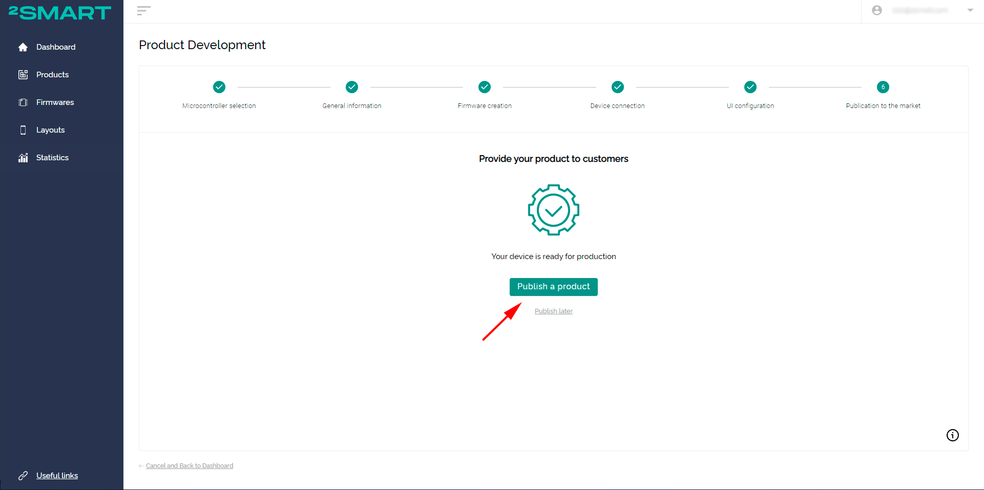
When using the wizard, click “Publish a product”:
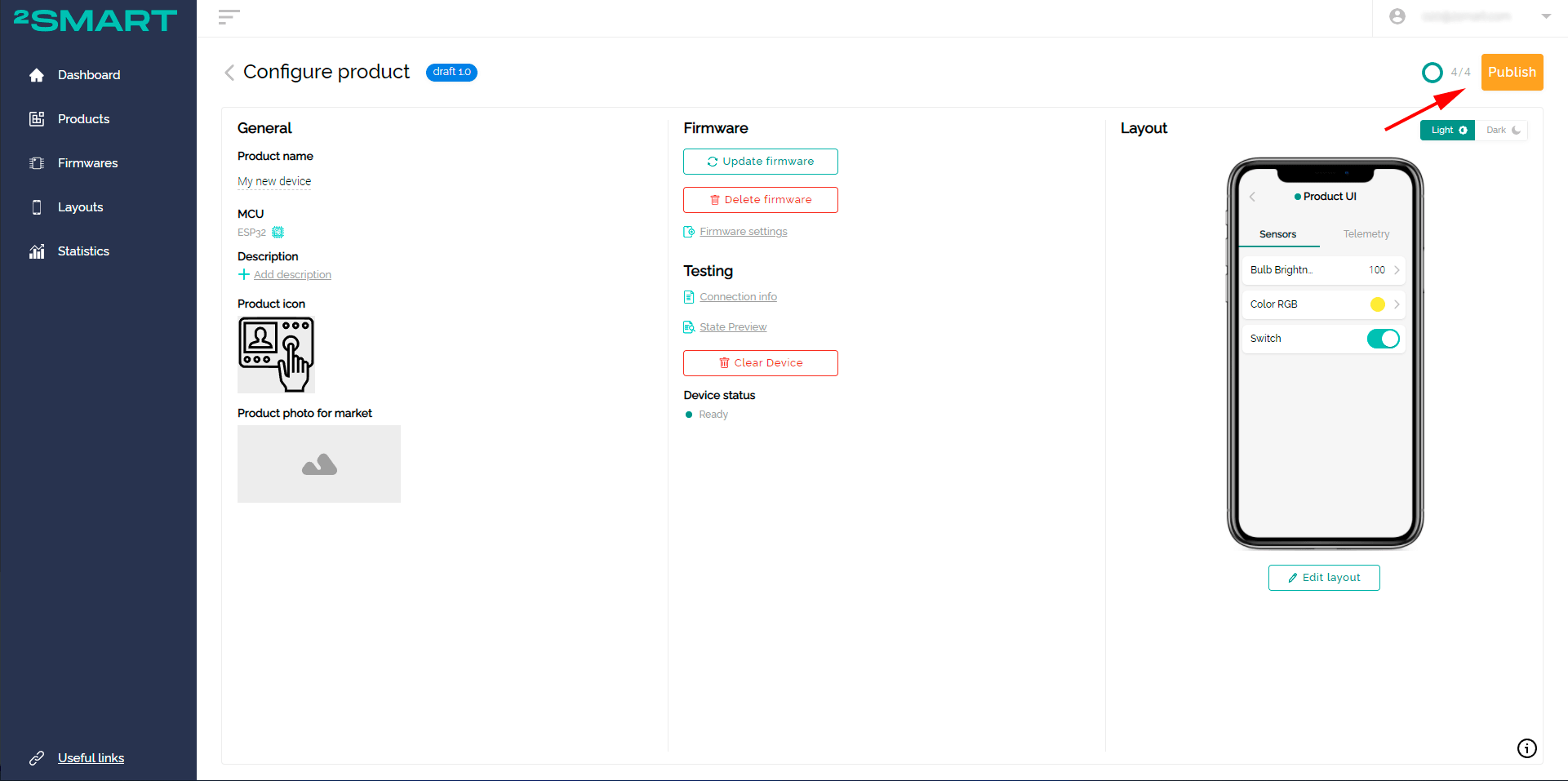
When using the product page, click the “Publish” button:
You can connect your cloud devices to the full smart home system 2Smart Standalone using the integration mechanism with the help of a unique bridge.
You can also use the 2Smart business platform if your solution is similar to the cloud platform for EV charging management. The business platform allows you to manage your company and its subsidiaries, users, their roles in the system, etc.
Don't forget to share this post!
Read Next

 2Smart Cloud for ESP32 microcontroller: functionality and operating instructions")


")


Let’s dive into your case
Share with us your business idea and expectations about the software or additional services.
